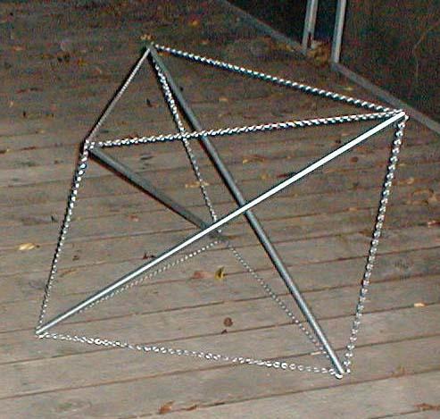
Excerpt from photo by Maxim Schrogin of his model
On November 17, 2003, Maxim Schrogin sent me an email inquiring if I could compute the three-fold tensegrity prism configuration which gave the maximum clearance to the struts. (Maxim uses the term "tetrahedron" to refer to what I call a three-fold tensegrity prism. After a short exchange, we figured out we were talking about the same thing.) When I looked into it, I found a ratio of the side tendon length to the end tendon lengths of about .84 did the trick giving a clearance of .1547 for a unit-length strut. I speculated that if I had carried the calculation out to more places I would find the exact number was sqrt(sin(45)), or 0.50.25 ≈ 0.840896. I also found the clearance didn't drop off quickly when the length of the side tendon was lengthened, a fact which I thought would be of interest to Maxim. The following table summarizes the values I found:
| Ratio of side tendon length to end tendon length |
Clearance for a unit-length strut |
|---|---|
| 0.70 | .151429 |
| 0.80 | .154447 |
| 0.84 | .154699 |
| 0.840896 | .154700 |
| 0.845 | .154700 |
| 0.85 | .154695 |
| 0.90 | .154328 |
| 1.00 | .152232 |
| 1.20 | .144862 |
| 1.50 | .131147 |
I sent selected values of this information to Maxim, and on November 27 he responded with photographs containing the above image of a three-fold prism built to the maximum-clearance specification. On seeing the model, it hit me that the struts looked orthogonal, so I returned to my computations to see if this was true, and it was, almost, at least at my mystical sqrt(sin(45)) point.
I hacked my software to provide greater accuracy for the clearance value, and found my mystical sqrt(sin(45)) point differed significantly from the point where orthogonality of the struts was reached, and that the orthogonality point was the point where maximum clearance was obtained. So, discarding mysticism, I took up the new number as the maximum-clearance point and settled for an approximate decimal representation. The values corresponding to the orthogonal point and my mystical point are:
| Ratio of side tendon length to end tendon length |
Clearance for a unit-length strut |
Angle (in degrees) between adjacent struts |
Strut length for unit-length end tendons |
|---|---|---|---|
| 0.843400773893 | 0.154700538380 | 90.0000000000 | 1.36602540378 |
| 0.840896415253 | 0.154699742518 | 90.1298086151 | 1.36448060432 |
The orthogonality of the struts struck me as the interesting property here. I could see employing the prism as a joint for the vertices of a sort-of tensegrity cube or rectangular lattice. I say "sort-of" because struts would interconnect between the prism joints and not be discontinuous as in the tensegrities I am accustomed to. In some sense, the lattice would be almost the opposite of the usual tensegrity: continuous compression and discontinuous tension instead of continuous tension and discontinuous compression. Well discontinuous tension anyway. What's happening with the compression I find hard to say.
In considering rectangular lattices, I was reminded of Kenneth Snelson's three-dimensional weaving illustrations, Bucky's lattice of tensegrity icosahedra (Synergetics Fig. 784.20) and the long struts in David Ratcliff's endless-bridge and tower structures where they are braced periodically by tendons.
My ultimate goal in this investigation was to construct a cube using the above-described three-fold prism configuration to brace the vertices. In addition, I planned to compute the three-fold, four-fold and five-fold prism configurations which will serve as vertices for the Platonic polyhedra. I finally decided to leave the computation of joints for Platonic polyhedra besides the cube for another lifetime, but if you continue reading this narrative, you'll eventually find a photo of the cube I assembled using this technique.
Before I constructed the cube using hardwood stakes and nylon twine, I made a simple dowel-and-fishing-line instance of the prism to help orient myself. A photo of the three-fold prism instance I constructed (working from the Datasheet for Three-fold Tensegrity Prism With Orthogonal Struts) is below. The photo is taken from a view down one of the struts which points up their orthogonality. (This model is also available on the Tensegrity Viewer as "3-Fold Orthogonal Prism".)

To further orient myself, I contemplated a couple tensegrity cubes (or snub cube as Anthony Pugh calls them) and assembled one. The subject of the Zig-Zag Tensegrity Cube Datasheet I just contemplated without actually assembling. The subject of the Orthogonal Tensegrity Cube Datasheet I actually assembled. The tendon topology for the orthogonal cube is the same as for the zig-zag cube. The struts are routed differently. Both of these structures are included in Allen Back's and Bob Connelly's Catalogue of Symmetric Tensegrities: the zig-zag cube is Example 6.1 of Conjugacy Class 6 of Group S4Z2, and the orthocube is Example 1.4 of Conjugacy Class 1 of Group A4Z2.
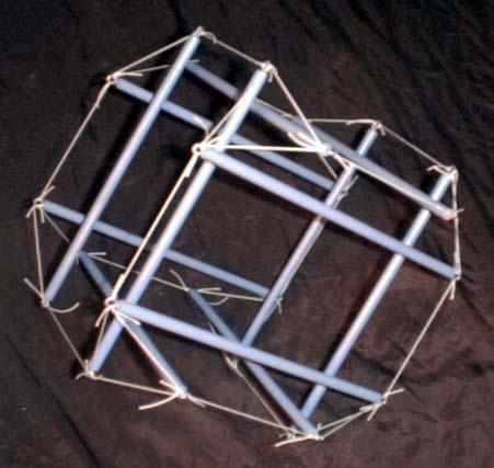
Above is the photo of the orthogonal tensegrity cube I assembled. I tried to photograph it from its good side so its cubicalness is not so readily apparent. It's almost as if the tensegrity icosahedron had undergone mitosis. Like the zig-zag structure it is a variation of, and unlike the tensegrity icosahedron, it is jiggly.
Buckminster Fuller shows a diamond version of the tensegrity cube in Synergetics (see Fig. 724.10). Initially I thought it was topologically identical to the tensegrity cuboctahedron which Hugh Kenner displays in his book Geodesic Math and How to Use It (see Fig. 3.4a on p. 21), in other words a diamond version of the zig-zag cube whose datasheet is referenced here. On closer examination however, I saw it was rigged differently. In the caption to his figure, Bucky refers to his cube as "unstable". I imagine that's true if one make the triangles small enough in relation to the strut lengths, but certainly at the size I use it's a stable structure.
When I went to construct a version of the orthogonal cube which uses tensegrity prisms to brace its vertices, I found the ad hoc adjustment of the tendon lengths I did in the Datasheet for Three-fold Tensegrity Prism With Orthogonal Struts didn't work very well for hardwood stakes and nylon twine. The ad hoc adjustment takes into account the fact that the tensegrity members don't really all meet at a point, but are connected at discrete places which differ slightly from each other. I think the poor performace of my ad hoc adjustments was due to the small length of the tendons when compared to the diameter of the struts.
It turned out that a very simple model for the hub connections was possible. This made the decision to incorporate the hub connections directly into the mathematical programming problem fairly painless. This done, no ad hoc adjustments were necessary. The result was the Second Datasheet for Three-fold Tensegrity Prism With Orthogonal Struts. I didn't use coordinate permutations in these new computations. This allowed me to transform the coordinate values so they were as convenient as possible for the POV-Ray models I used to generate my ray-traced diagrams.
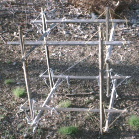
The photo above shows the finished product. I tied four of the cubic vertices with white nylon twine and four of them with braided yellow nylon twine. The braided twine was much easier to work with though it is more elastic. Its mechanical properties seem similar to the white twine when it's used at the same tensions. After many diversions, I finished assembling this on April 16, 2004.
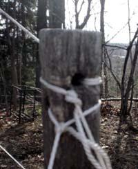
In tieing the tendons, I found that, in order to get an accurate tendon length, it was important to pay attention to which way the tendon was pulling relative to the strut in the final configuration. If I looped the twine around the side of the strut most opposite to the direction the twine was pulling, as is the case with the knot outside the upper hole of the hub in the photo below, the knot stayed in place and kept the tendon length accurate. If I looped the twine around the side of the strut closer to the direction the twine was pulling, as is the case with the knot outside the lower hole of the hub in the photo below, the knot wandered from where the twine exited the strut and the tendon didn't maintain the distance between the struts it tied properly.
With a tensegrity, particularly a simple one like the three-fold prism being used here, the final configuration isn't reached until the last tendon is tied; so, I had to tie an initial trial prism to ascertain the directions the tendons would take relative to the struts and how the struts would orient themselves relative to the tendons. This information could have been ascertained from my diagrams, but I had already tied a prism before I realized it was a factor I needed to take into account. As with the poor performance of the ad hoc adjustment for the hubs mentioned above, I think the reason I had to take extra care here was due to the short lengths of the tendons relative to the diameter of the struts.
When I showed Kenneth Snelson the above cube photo, he sent me back three from explorations he had done which are in a similar vein. They are in my gallery of Kenneth Snelson Models: Marching Three-Strut Piece 1968, Ninety-Degree Module Experiment July 1972 and Sprawl Piece 1974. Snelson's description of his Ninety-Degree Module Experiment reminded me of a sculpture I had thought of doing with my cubic module which would have been a semi-circular arch with the cubes placed using Bresnaham's "Midpoint Circle Algorithm" from computer graphics (James D. Foley et al., Computer Graphics: Principles and Practice, 2nd ed. in C, Reading, Massachusetts: Addison-Wesley Publishing Co., 1996, pp. 83-87) at a low resolution, perhaps entitled "Homage to the Circle-Drawing Algorithm." A good algorithm deserves a monument.
In addition to this cubic lattice, I've also been interested in developing a 60° lattice based on this sort of joinery, something on the order of the Tetrahedral Spaceframe Weave which Kenneth Snelson exhibits. Certainly making a tetrahedron would be simple enough, but I haven't quite grasped how to organize the lattice. I'm not even sure it's possible. It may be that such a lattice requires the lattice lines to intersect each other, and maintaining the spacing that this tensegrity joinery requires is impossible.
Joints based on other sorts of tensegrity besides prisms are possible. For example, I've considered constructing a diamond lattice based on a joint derived from the Two-Stage X-Module Column. That too may have to wait for another lifetime.
The Cubic Lattice Segment appeared in the exhibition "Contemporary Artists Look at Historic Shirley" at the Shirley Historical Society's Lucy Longley Memorial Building, July 9, 2004 - September 4, 2004. Also included in the exhibit were Maxim's photo detail and reproductions of several of my tensegrity graphics.


