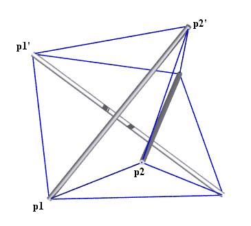
View of the Tensegrity Prism
with Point Labels
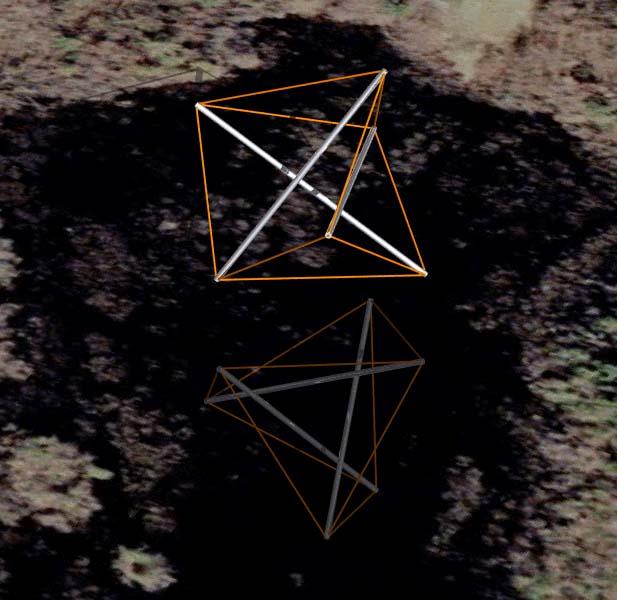
Tensegrity Prism Reflected in Spruce Swamp
Shirley Center, Massachusetts
        Member Descriptions
        [name, end point names, weight (if in objective function),
        second power of length (if a constraint), member category,
        Obj/Con/Exc (put in objective function, use as a constraint or
        exclude from computations), flags]
        For assembly purposes, only the name and end point names are
        of interest.  The other information may be of interest after
        A Practical Guide to Tensegrity Design has been consulted.

# strut
<Member> strut     p2' p1  -1.0      0.0      1 Obj CalcClear Inelastic *

# interlayer tendon
<Member> side      p1' p1   1.0      sqr(0.843400773893062) 3 Con CalcClear *

# bottom tendon
<Member> bottom    p2  p1   1.0      sqr(1.0) 2 Con CalcClear *

# top tendon
<Member> top       p2' p1'  1.0      sqr(1.0) 4 Con CalcClear *


        In-Situ Member Lengths
        These are the lengths of the members when they are in place
        and prestress is applied.  The strut lengths are from
        screw-eye center to screw-eye center, as are the tendon lengths.
        The values are in model units.

    strut:      1.36603      side:     0.843401    bottom:            1
      top:            1


        Relative Member Force Magnitudes
        These values are useful for developing an assembly
        strategy for the structure.  The tighter tendons are much
        easier to tie in place early on, while the looser tendons
        can be left to the last.  This information is also used
        to adjust tendon lengths since the measured length of a tendon
        will be shorter for a highly-stressed tendon with the same
        in-situ length as a tendon which is not so stressed.

    strut:     -1.36603      side:     0.843401    bottom:      0.57735
      top:      0.57735


        Construction Lengths (in millimeters and halves)
        The construction length of a tendon is less than the in-situ
        length since when the tendon is measured off it isn't under
        any prestress force.  The construction length for the strut
        represents the length of the 5/16-inch-diameter wooden dowel.
        The tendons were made of braided nylon fishing line.
        Prestress forces were assumed not to affect strut lengths.

        Elongation of Tendon of Unit Cross Section
        Under Force of Average Magnitude (fraction)> .02
        Length Scale Factor> 319/1.36602540378379
        Strut and Tendon Hub Adjustments - s;t> 6.5 4
        (The 6.5 mm adjustment for the strut is the amount
         the screw-eye center extends from the dowel.  The 4 mm
	 adjustment for the tendon is half the outer diameter of the
         screw eye.)

    strut: 306 0      side: 184 1    bottom: 221 1       top: 221 1


        Alternative Construction Lengths (inches, 16ths and 32nds)
        The struts here were cut from 1-inch by 1-inch hardwood
        garden stakes.  The tendon were made of single strands
        of twisted #18 nylon twine.  Its behavior under stress
        is highly non-linear, so a look-up table
        was used to compute strains.  This actually didn't work
        out very well.  The ad hoc adjustments didn't do the job
        probably because they were so large in relation to the
        tendon lengths.

        Average Tendon Force Magnitude (chart units)> 20
        Length Scale Factor> 12/1.36602540378379
        Strut and Tendon Hub Adjustments - s;t> 0 0.5

    strut:  12  0 0   side:   5 12 1 bottom:   7  3 0    top:   7  3 0
View of the Tensegrity Prism
with Point Labels
Tensegrity Prism Reflected in Spruce Swamp
Shirley Center, Massachusetts
structure file:  tprism/x3prism_ortho.rc
 variable file:  tprism/x3prism_ortho.dat
    digit list:  src/mm.dls (for mm and halves)
    digit list:  src/standard.dls (for inches, 16ths and 32nds)
|
CONTACT:
Bob Burkhardt
Tensegrity Solutions
Box 426164
Cambridge, MA 02142-0021
USA
e-mail: bobwb@juno.com