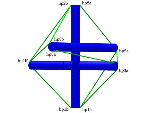
View of the Tensegrity Prism
with Point Labels
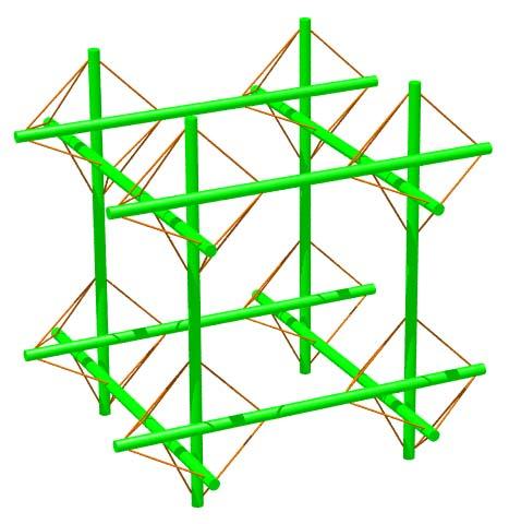
Cell of Cubic Lattice Constructed using
Tensegrity Prisms as Joints
structure file: tprism/x3prism_orthoj2.rc variable file: tprism/x3prism_orthoj2.dat digit list: src/standard.dls |
        Hub Connectivity
        This shows how vectors (v1, v2, v3) are applied to the
        strut end points (p1, p1', p2, p2', p3, p3') to derive
        hub points (hp1a, hp1b, ...).  Hub points are where tendons
        are connected to the strut.

<VecPt>    hp1a   p1   +  v1
<VecPt>    hp1b   p1   -  v1
<VecPt>    hp1a'  p1'  +  v3
<VecPt>    hp1b'  p1'  -  v3
<VecPt>    hp2a   p2   +  v2
<VecPt>    hp2b   p2   -  v2
<VecPt>    hp2a'  p2'  +  v1
<VecPt>    hp2b'  p2'  -  v1
<VecPt>    hp3a   p3   +  v3
<VecPt>    hp3b   p3   -  v3
<VecPt>    hp3a'  p3'  +  v2
<VecPt>    hp3b'  p3'  -  v2


        Member Descriptions
        [name, end point names, weight (if in objective function),
        second power of length (if a constraint), member category,
        Obj/Con/Exc (put in objective function, use as a constraint or
        exclude from computations), flags]
        For assembly purposes, only the name and end point names are
        of interest.  The other information may be of interest after
        A Practical Guide to Tensegrity Design has been consulted.
        This figure was computed without benefit of symmetry transforms,
        but everything turned out very symmetric nevertheless.

# struts
<Member> strut1    p2'   p1      -1.0  sqr(12.0) 1 Con CalcClear *
<Member> strut2    p3'   p2      -1.0  sqr(12.0) 1 Con CalcClear *
<Member> strut3    p1'   p3      -1.0  sqr(12.0) 1 Con CalcClear *

# side tendons
<Member> side1     hp1a' hp1b     1.0  0.0       3 Obj CalcClear *
<Member> side2     hp2a' hp2b     1.0  0.0       3 Obj CalcClear *
<Member> side3     hp3a' hp3b     1.0  0.0       3 Obj CalcClear *

# end tendons
<Member> end1      hp2a  hp1a     1.0  sqr(8.38288) 2 Con CalcClear *
<Member> end2      hp3a  hp2a     1.0  sqr(8.38288) 2 Con CalcClear *
<Member> end3      hp1a  hp3a     1.0  sqr(8.38288) 2 Con CalcClear *
<Member> end1'     hp2b' hp1b'    1.0  sqr(8.38288) 4 Con CalcClear *
<Member> end2'     hp3b' hp2b'    1.0  sqr(8.38288) 4 Con CalcClear *
<Member> end3'     hp1b' hp3b'    1.0  sqr(8.38288) 4 Con CalcClear *


        Hub Constructs
        These items are just vectors corresponding to each of the
        struts.  At some point the software will be modified so
        these items aren't necessary since it should be possible
        to treat any member as a vector without explicit constructs.

<DiffVec>    strut1v    p2'     p1
<DiffVec>    strut2v    p3'     p2
<DiffVec>    strut3v    p1'     p3


        Hub Constraints
        These are constraints the hub vectors must meet.  Each
        vector must be orthogonal to its strut and 0.5 inches long.

<VecDotVec>  hubdot1    strut1v v1  1.0  0.0         Con
<VecLength>  hublength1 v1          1.0  sqr(0.5)    Con
<VecDotVec>  hubdot2    strut2v v2  1.0  0.0         Con
<VecLength>  hublength2 v2          1.0  sqr(0.5)    Con
<VecDotVec>  hubdot3    strut3v v3  1.0  0.0         Con
<VecLength>  hublength3 v3          1.0  sqr(0.5)    Con


        In-Situ Member Lengths
        These are the lengths of the members when they are in place
        and prestress is applied.  These are raw unadjusted values and
        assume the hubs of the structure are single points.  The
        values are in model units.

   strut1:           12    strut2:           12    strut3:           12
    side1:      6.65617     side2:      6.65617     side3:      6.65617
     end1:      8.38288      end2:      8.38288      end3:      8.38288
    end1':      8.38288     end2':      8.38288     end3':      8.38288


        Relative Member Prestress Force Magnitudes
        These values are useful for developing an assembly
        strategy for the structure.  The tighter tendons are much
        easier to tie in place early on, while the looser tendons
        can be left to the last.  This information is also used
        to adjust tendon lengths since the measured length of a tendon
        will be shorter for a highly-stressed tendon with the same
        in-situ length as a tendon which is not so stressed.

   strut1:     -10.4407    strut2:     -10.4407    strut3:     -10.4407
    side1:      6.65617     side2:      6.65617     side3:      6.65617
     end1:      4.33197      end2:      4.33197      end3:      4.33197
    end1':      4.33197     end2':      4.33197     end3':      4.33197


        Construction Lengths
        (stakes and #18 twisted nylon twine (white) --
         inches, 16ths and 32nds)
        The construction length of a tendon is less than the in-situ
        length since when the tendon is measured off it isn't under
        any prestress force.  The construction length for a strut
        represents the distance between tendon attachment points
        on the strut assuming both attachment points are on the same
        side of the strut.  Prestress forces are assumed to affect
        tendon lengths and not strut lengths.  For this particular hub
        geometry, the ad hoc adjustment used in the first datasheet
        didn't work very well.  Here no ad hoc adjustment is necessary
        since the hubs are included explicitly in the mathematical
        programming problem.  The struts were cut from
        1-inch by 1-inch hardwood garden stakes.  The behavior
        of the #18 twisted nylon twine under stress is highly non-linear,
        so a look-up table was used to compute strains.

        stress-strain chart: v04oct_d/wellingtn.ssc
        Average Tendon Force Magnitude (chart units)> 20
        Length Scale Factor> 1.0
        (Things are scaled so model and construction units are the same.)
        Strut and Tendon Hub Adjustments - s;t> 0 0
        (As seen above, hub connections were handled explicity in
         the mathematical programming problem, so no ad hoc
         adjustment is needed here to account for the hub connections.)

   strut1:  12  0 0    strut2:  12  0 0    strut3:  12  0 0
    side1:   6  0 0     side2:   6  0 0     side3:   6  0 0
     end1:   7 12 0      end2:   7 12 0      end3:   7 12 0
    end1':   7 12 0     end2':   7 12 0     end3':   7 12 0


        Alternate Construction Lengths
        (stakes and #1 braided nylon twine (yellow) --
         inches, 16ths and 32nds)
        For my version of the structure, I tied half the prisms (4)
        with this twine, and half with the twisted twine.  This
        twine looks nicer and doesn't unravel like the twisted.
        This twine is also more elastic which is why the construction
        lengths are shorter.  When used at the same tensions,
        as I do here, the mechanical properties of the braided twine
        seem equivalent to the white nylon twine..  The braided
        twine's behavior under stress is different from the
        behavior of twisted twine, so a different look-up table
        was used to compute strains.

        stress-strain chart: v02oct_s/evans.ssc
        Average Tendon Force Magnitude (chart units)> 20
        Length Scale Factor> 1.0
        Strut and Tendon Hub Adjustments - s;t> 0 0

   strut1:  12  0 0    strut2:  12  0 0    strut3:  12  0 0
    side1:   5 13 1     side2:   5 13 1     side3:   5 13 1
     end1:   7  9 0      end2:   7  9 0      end3:   7  9 0
    end1':   7  9 0     end2':   7  9 0     end3':   7  9 0
View of the Tensegrity Prism
with Point Labels
Cell of Cubic Lattice Constructed using
Tensegrity Prisms as Joints
structure file: tprism/x3prism_orthoj2.rc variable file: tprism/x3prism_orthoj2.dat digit list: src/standard.dls |
CONTACT:
Bob Burkhardt
Tensegrity Solutions
Box 426164
Cambridge, MA 02142-0021
USA
e-mail: bobwb@juno.com