This isn't what people usually are referring to when they talk about a tensegrity tetrahedron. A rendering of the structure traditionally called a tensegrity tetrahedron (first exhibited by Francesco della Sala in 1952):
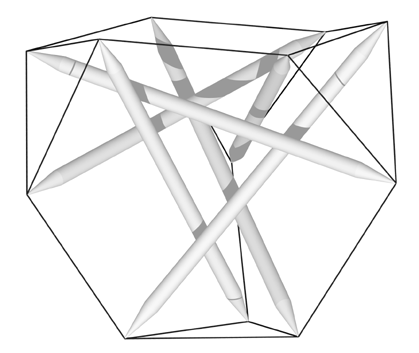
Tensegrity Tetrahedron from Section 2.4 of
A Practical Guide to Tensegrity Design
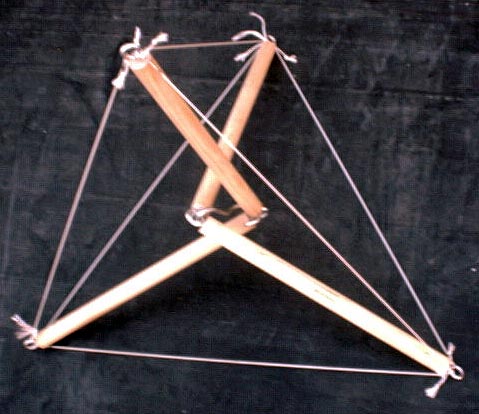
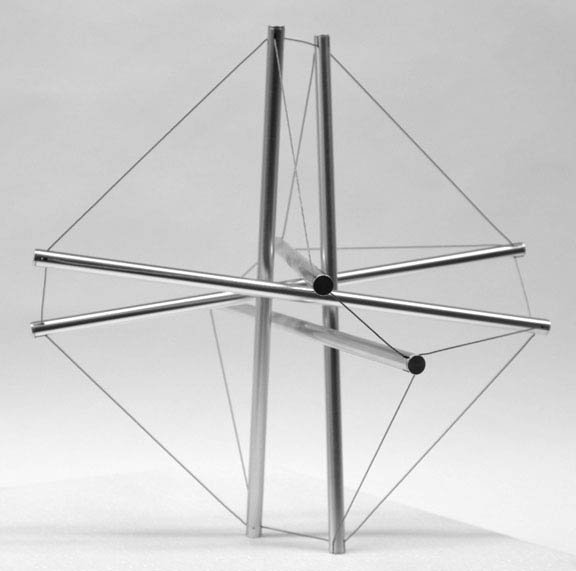
In building the photographed model above, I was interested in building a structure like Fuller's tensegrity mast and thought the model in the photo might be simpler to deal with than the usual module where four tetrahedral radii meet at the center. Here they meet pairwise. An interest of Phil Earnhardt in a structure that mimiced the human spine motivated the exploration. I thought a mast with these modules and using elastic tendons might be a good candidate, but investigations showed it would probably be too unstable to serve as a good lecture model if built with elastic tendons.
On November 14, 2005, I built the above model with nylon twine. It seems stable enough. Up to this point, I have only worked with floating-compression structures where the struts are simple linear components and don't have hinges. Some would term the typical floating-compression structure as a Class 1 structure as opposed to this design which is a Class 2 design (see Narongsak Kanchanasaratool and Darrell Williamson's paper in the References section of Definition and Classification of Tensegrities) since there are nodes where two struts meet instead of just one.
For the center, I used a specially twisted hook. I show a detail of the central hub below. The screw eyes aren't lined up precisely as I had envisioned, but close enough.
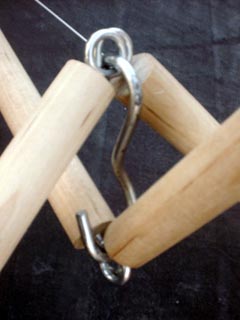
Central hub detail
Val Gómez Jáuregui's bridge design got me interested in tensegrities built with hinged struts as I could imagine the struts in his design joined pairwise at the top and hinged together since they are already so close there. The hinged strut design still seems to retain a lot of simplicity since a hinge is fairly simple. I don't think a universal joint would be necessary.
In a posting to bit.listerv.geodesic, Spencer Hunter notes the similarity of this structure with a module he's developed, and also one developed by René Motro.
The datasheet was completed October 20, 2005, (revised November 14) and I completed the design on January 4, 2005. This design (which actually should be attributed to Sadao and Price -- see below) and the della Sala tetrahedron are available for inspection in all the tensegrity viewers.
Discussions with Spencer Hunter prompted me to put together another datasheet on November 21, 2005, for a smaller-scale version with a relatively longer central tendon. I built it the next day. Here's a photo:
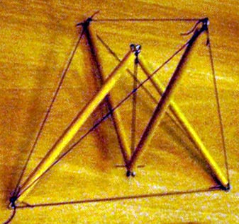
Tensegrity Tetrahedron (2nd version)
Once it was assembled, I had to exercise it a bit to get things lined up properly. This I attribute to the nylon fishing line's memory properties. The structure isn't as easy to destabilize as I thought it would be. Even though the relatively longer central tendon locates the hubs close to the face, the hub resists mightily going in that direction. Spencer Hunter's maneuver of axially compressing one of the four higher stressed tendons does collapse it easily; however, it pulls right back together, and I can handle it and drop it on a face from a height of six inches with no problem. This could be a model for a deployable structure.
My conclusion is relative shortness of the central tendon, inelasticity of the tendons and higher prestresses contribute to the stability of this structure, and a judicious mixture of these factors can result in a very stable structure like the first one I assembled. In retrospect, I would have used a higher prestress in the second structure. I could have gotten away with 3% easily rather than the 2% average tendon elongation I customarily use when working with fishing line. Perhaps the lack of tension in those two tetrahedral tendons that close the V's is making me incautious though. It seems a well-buffered structure. While those two tendons are rather low in tension there seems to be absolutely no tendency for them to go slack, and the central tendon is surprisingly highly stressed.
Later I found that this was the manner in which the units for the mast for Buckminster Fuller's 1959 Museum of Modern Art exhibition were constructed by Shoji Sadao and Edison Price. See the second photo (the mast is on the far left) in R. Buckminster Fuller, "Tensegrity," Portfolio and Art News Annual, No. 4 (1961), pp. 112-127, 144, 148. In that case, the central tendon was, thankfully for MoMA patrons and staff, relatively short and the tendons inelastic.
I have also found Tom Flemons uses Fuller's mast variation on Snelson's X-Piece to model the human spine. Tom's elastic implementation sensibly sticks with the Class 4 modules that everyone except Sadao and Price seem to use. So I'm afraid I haven't been very original here, but I have had some fun.
Not surprisingly, Kenneth Snelson has also thought about the tensegrity tetrahedron. The first photo of interest I got from him is a variation on the usual tensegrity tetrahedron like the one in my book. He prefaced the photo with ("Re: Tensegrity on and on", January 12, 2006), "To configure the truncated tetrahedron network Bucky-style is equivalent to attaching the standard six-strut's tendons in this fashion:"
Tensegrity Tetrahedron (Snelson variation)
Photo courtesy of Kenneth Snelson
"Which works out poorly as you can discover by making such a figure." I wasn't curious enough to make it myself, but it did look curiously different. It took me some time to realize he'd just changed some tendon lengths in the figure I was used to looking at.
Later I quizzed him on the photo of the vitrine with his works at the 1959 Museum of Modern Art exhibition mentioned above. In particular I was curious about a small tetrahedral-looking tensegrity I saw. It turned out that again it was a variation on a familiar structure (the Two-Stage X-Module Column this time) with just some tendon lengths changed. Here's a photo ("Re: Tensegrity on and on", March 6, 2006) of his assembly documentation for the structure:
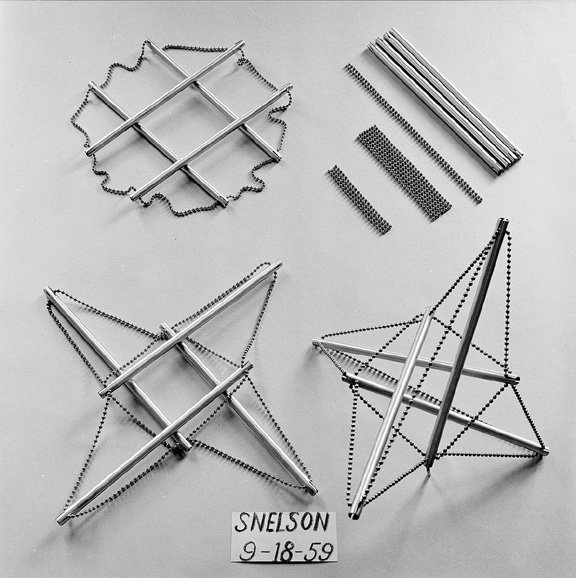
Bead X-Module Tetrahedron 1959
Photo courtesy of Kenneth Snelson
On March 13, 2006, I did computations for a similar structure. I was able to compute it so the vertices matched a regular tetrahedron and each strut had one end touching the face of the implicit tetrahedron. On September 10, 2007, I prepared a datasheet for this structure, and assembled a model on September 18. After stepping on this model and fracturing one of the struts and noticing how flimsy the strut-screw-eye nexus was, on October 22 I augmented the datasheet with another realization which used thinner dowels and simple nails in the ends rather than screw eyes. I completed assembly the same day. A photo of the model is below:
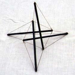
BURKHARDT
10-22-07
I am not giving up on the screw-eye approach which seems most useful when a lot of tendons meet at a hub. But I think, at least for the way I am using the eyes, bigger ones than size 217½ are needed to work, and for larger screw eyes, thicker dowels are necessary. I like the ethereal appearance the thinner dowels lend to the models. Perhaps epoxying the small screw eye when fastening it to the dowel would strengthen that joint.
The approach with nails in the ends of the dowels is not without its problems. I have had trouble with the 3/16" dowels splitting when I drive the nails into the end. Starting the hole with a very small drill might help.
You can find models of the two Snelson tetrahedra in all of the tensegrity viewers.
More recently (September 6, 2009), Marcelo Pars shared with me his latest tensegrity studies of the tetrahedron which are worthy additions to his past work. I am going to build a simple version of one of his studies:
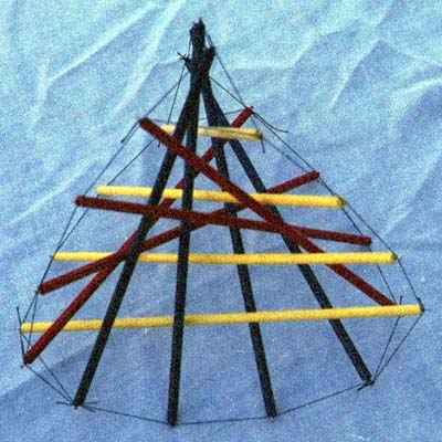
3v Pars Tensegrity Tetrahedron
On October 30, 2009, I prepared a datasheet. The raytrace in the datasheet really does not do the design justice, although I hope it makes it more comprehensible. The above photo gives another point of view. Looking at it in one of the tensegrity viewers is suggested (look for "Tensegrity Tetrahedron (Pars)"). But, as with so many tensegrity structures, there is nothing like having a model in hand.
I assembled the model on December 1, 2009. I didn't bother printing out the datasheet. I just kept in mind a cube and the four vertexes that correspond to the tetrahedron. I made one false start which I had to back out of. Obviously one wants to start by creating three sub-assemblies of four struts, a tendon on one sub-assembly being omitted so it can be merged with the other two. It also turned out to be important to tie the first two sub-assemblies together as completely as possible before introducing the third one. This creates enough structure to ease the introduction of the final sub-assembly to complete the structure. With this approach, the assembly went easily enough.
I marveled even more at Marcelo's design with the model in hand. It strikes me as a sort of three-dimensional yin-yang.


