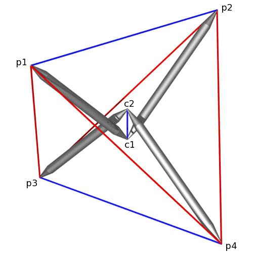
Tensegrity Tetrahedron Point Labels
structure file: tetra/tetra3.rc variable file: tetra/tetra3.dat |
        Member Descriptions
        [name, end point names, weight (if in objective function),
        second power of length (if a constraint), member category,
        Obj/Con/Exc (put in objective function, use as a constraint or
        exclude from computations), flags]
        For assembly purposes, only the name and end point names are
        of interest.  The other information may be of interest after
        A Practical Guide to Tensegrity Design has been consulted.

# struts
<Member> s1    c1   p1   -1.00   sqr(330)       1 Con *
<Member> s2    c1   p2   -1.00   sqr(330)       1 Con *
<Member> s3    c2   p3   -1.00   sqr(330)       1 Con *
<Member> s4    c2   p4   -1.00   sqr(330)       1 Con *

# tendons
<Member> t1-2  p1   p2    1.00   sqr(498.5297)  3 Con *
<Member> t1-3  p1   p3    1.00   sqr(498.5297)  2 Con *
<Member> t1-4  p1   p4    1.00   sqr(498.5297)  2 Con *
<Member> t2-3  p2   p3    1.00   sqr(498.5297)  2 Con *
<Member> t2-4  p2   p4    1.00   sqr(498.5297)  2 Con *
<Member> t3-4  p3   p4    1.00   sqr(498.5297)  3 Con *
<Member> tc    c1   c2    1.00   sqr(80)        3 Obj *


        In-Situ Member Lengths
        These are the lengths of the members when they are in place
        and prestress is applied.  The strut lengths are from
        screw-eye center to screw-eye center, as are the tendon lengths.
        The values are in model units.

       s1:          330        s2:          330        s3:          330
       s4:          330      t1-2:       498.53      t1-3:       498.53
     t1-4:       498.53      t2-3:       498.53      t2-4:       498.53
     t3-4:       498.53        tc:           80


        Relative Member Force Magnitudes
        These values are useful for developing an assembly
        strategy for the structure.  The tighter tendons are much
        easier to tie in place early on, while the looser tendons
        can be left to the last.  This information is also used
        to adjust tendon lengths since the measured length of a tendon
        will be shorter for a highly-stressed tendon with the same
        in-situ length as a tendon which is not so stressed.

       s1:     -61.0385        s2:     -61.0385        s3:     -61.0385
       s4:     -61.0385      t1-2:      17.8211      t1-3:      28.2843
     t1-4:      28.2843      t2-3:      28.2843      t2-4:      28.2843
     t3-4:      17.8211        tc:           80

        Average tendon force magnitude: 32.6827


        Construction Lengths (in mm and halves)
        The construction length of a tendon is less than the in-situ
        length since when the tendon is measured off it isn't under
        any prestress force.  The construction length for a member
        represents the distance between the locations where it
        departs from the hub.  The struts were cut from
        3/4-inch diameter hardwood dowel.  The tendons were made
        of single strands of twisted #18 nylon twine.  Its behavior
        under stress is highly non-linear, so a look-up table
        was used to compute strains.  Prestress forces were assumed
        to affect tendon lengths and not strut lengths.  For the tc
        member, a double hook was used that kept the screw-eye centers
        80 mm apart.

        stress-strain chart:  v04oct_d/wellingtn.ssc
        Average Tendon Force Magnitude (chart units)> 15
        Length Scale Factor> 1
        Strut and Tendon Hub Adjustments - s;t> 13 8
        (subtract 2*(13 mm) off strut lengths to get dowel lengths;
         subtract 2*(8 mm) off tendon lengths to get hub-adjusted
         in-situ tendon lengths)

       s1: 304 0        s2: 304 0        s3: 304 0        s4: 304 0
     t1-2: 460 1      t1-3: 451 0      t1-4: 451 0      t2-3: 451 0
     t2-4: 451 0      t3-4: 460 1        tc:  80 0
Tensegrity Tetrahedron Point Labels
structure file: tetra/tetra3.rc variable file: tetra/tetra3.dat |
CONTACT:
Bob Burkhardt
Tensegrity Solutions
Box 426164
Cambridge, MA 02142-0021
USA
e-mail: bobwb@juno.com