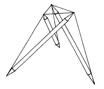
Figure 5.1: Tensegrity Tripod
A Practical Guide to Tensegrity Design
Table of Contents
5.1 Double-Layer Tensegrities:
Introduction
5.2 Double-Layer Tensegrities: Trusses
Take the finished t-prism introduced in Section 2.2 and remove the triangle of tendons corresponding to one of the ends. When pressed towards each other, the three free strut ends strongly resist the effort and stay apart. This composite compression member, a tensegrity tripod or t-tripod, can thus be attached to three hubs of a tensegrity structure and keep them apart. It is illustrated in Figure 5.1. When used to support a single-layer tendon network, the t-tripods' struts are outside the layer containing the three hubs, thus eliminating the intractable interference problems that can result in larger structures when simple two-hubbed struts lie in the same layer which they support.
|
Figure 5.1: Tensegrity Tripod |
Let the single-layer network supported by the t-tripods be spherical and composed of vertex-connected polylaterals.5 No more than one vertex is shared between adjacent polylaterals, and every vertex is shared by exactly two polylaterals. The apexes of the t-tripods could point out or in, but assume they point out. In addition to the continuous single-layer spherical network, there is a discontinuous outer network formed by the tendon triangles of the apexes of the t-tripods being used as compression members. Call these apex tendons the outer convergence tendons, and call the t-tripod tendons connecting these triangles with the opposite ends of the t-tripod's struts the primary interlayer tendons.
To lend more stability to the structure, the outer network is completed by binding together the t-tripod apexes using another set of tendons called the outer binding tendons. Let the outer network have exactly the same topology as the inner network though of course the lengths of the outer network's tendons are different. Untwisting a t-tripod removes the three free ends of the t-tripod even further from each other. Thus, if possible, the outer convergences should be bound together in such a way that tensioning the outer binding tendons untwists the t-tripods. In this way, while the outer network of tendons presses in, the inner network will press out under the impetus of its expanding compression members, the untwisting t-tripods.
When the struts meet on the inner network, they form convergences where struts from several different t-tripods are connected together with tendons that form a polylateral. These tendons are the inner convergence tendons and topologically they are equivalent to the outer binding tendons. The remaining tendons of the inner network are the inner binding tendons whose polylaterals alternate with those of the inner convergence tendons. They are topologically equivalent to the outer convergence tendons, which means they are triangles in this example.
A t-prism doesn't need to be based on a triangle; any polylateral will do, and eliminating the tendons on one end will generate a "t-polypod" which can be used just like the t-tripod as a complex compression member to support a tendon network. Close examination of the tendons of an inner convergence will show that, in conjunction with the converging struts, they form an inward-pointing t-polypod when the appropriate tendons are added connecting the convergence polylateral to the opposite ends of the struts. These connecting tendons are the secondary interlayer tendons and complete the truss network.
With this method of generating a tensegrity truss, the topology of the inner and outer layers will not only need to be identical, the tendon triangles and polylaterals which make up each layer will need to be divisible into two groups which alternate. A triangle or polylateral from one group will need to be completely surrounded by polylaterals from the other group. An identical truss could have been generated by starting with the inward-pointing t-polypods supporting a complete outer network and then binding their apexes together and adding interlayer tendons to generate the outward-pointing t-tripods.
The end result is a rigid tensegrity space frame aimed at extremely large-scale applications like the covering of entire settlements or the superstructure of a space station. Though it is possible to have polylaterals alternating with polylaterals in the spherical network instead of one of the sets of polylaterals being restricted to triangles, an emphasis on triangles may yield a more rigid structure. The complexity of this tensegrity requires that designs be checked carefully to make sure struts and tendons have sufficient clearance and that member forces are appropriate, i.e. tendons are in tension and struts are in compression.
5 The term "polylateral" is used rather than polygon since a polygon is planar and the figure referenced here may not be. The polylateral concept envisions a ring of vertexes, each vertex corresponding to a hub in a tensegrity. The vertexes in the ring are continuously connected pair-wise by edges, each edge corresponding to a tendon in a tensegrity. Each edge connects two vertexes, and each vertex is connected to two edges. Flattening a polylateral would yield the boundary of a polygon, and a triangular polylateral is distinguished by the fact that it can always be considered the boundary of a polygon, the triangle. Fuller uses the term "polyvertexion" as an operational substitute for polyhedron with qualifications that seem applicable here as well. See Fuller92, pp. 130-131, Fig. 6.6 (p. 132) and p. 233.
Table of Contents
5.3 Double-Layer Tensegrities:
Geodesic Networks