        Hub Constructs
        These items are just vectors corresponding to each of the
        struts (see Member Descriptions below).  Some are normalized.
        The normalized -- to 1 inch (stvn..) and 0.25 inch (stvq..) --
        versions are used as offsets for constructing hub points.  Some
        (hva..) are cross products, constructed to be orthogonal to the
        primary vectors (hv..).

<DiffVec>    stv13      p1A     p3a
<ScaledVec>  stvn13     stv13   1/29
<ScaledVec>  stvq13     stv13   1/(29*4)
<DiffVec>    stv24      p4a     p2A
<ScaledVec>  stvn24     stv24   1/29
<ScaledVec>  stvq24     stv24   1/(29*4)
<DiffVec>    stv35      p3A     p5a
<ScaledVec>  stvn35     stv35   1/29
<ScaledVec>  stvq35     stv35   1/(29*4)
<DiffVec>    stv46      p4A     p6a
<ScaledVec>  stvn46     stv46   1/29
<ScaledVec>  stvq46     stv46   1/(29*4)
<CrossVec>   hva13      hv13 stvn13
<CrossVec>   hva24      hv24 stvn24
<CrossVec>   hva35      hv35 stvn35
<CrossVec>   hva46      hv46 stvn46


        Hub Constraints
        These are constraints the primary vectors must meet.
        Since the tensegrity is constructed of 1-7/16 inch square
        stock, the vectors are constrained to be 0.71875 inches
        long and orthogonal to their respective struts.

<VecDotVec>  hvdot13    stv13   hv13  1.0  0.0             Con
<VecLength>  hvlen13    hv13          1.0  sqr(0.71875)    Con
<VecDotVec>  hvdot24    stv24   hv24  1.0  0.0             Con
<VecLength>  hvlen24    hv24          1.0  sqr(0.71875)    Con
<VecDotVec>  hvdot35    stv35   hv35  1.0  0.0             Con
<VecLength>  hvlen35    hv35          1.0  sqr(0.71875)    Con
<VecDotVec>  hvdot46    stv46   hv46  1.0  0.0             Con
<VecLength>  hvlen46    hv46          1.0  sqr(0.71875)    Con


        Hub Connectivity
        This shows how the primary vectors and Hub Constructs are
        applied to the primary points (p..) to derive tendon attachment
        points (hp... and hpa...).

# intermediate hub points
<VecPt> pq1A  p1A + stvq13
<VecPt> pq3a  p3a + stvq13
<VecPt> pq2A  p2A - stvq24
<VecPt> pq4a  p4a - stvq24
<VecPt> pq3A  p3A + stvq35
<VecPt> pq5a  p5a + stvq35
<VecPt> pq4A  p4A + stvq46
<VecPt> pq6a  p6a + stvq46

# tendon attachment points
<VecPt> hp1A+ pq1A + hv13
<VecPt> hp1A- pq1A - hv13
<VecPt> hp3a+ pq3a + hv13
<VecPt> hp3a- pq3a - hv13
<VecPt> hp2A+ pq2A + hv24
<VecPt> hp2A- pq2A - hv24
<VecPt> hp4a+ pq4a + hv24
<VecPt> hp4a- pq4a - hv24
<VecPt> hp3A+ pq3A + hv35
<VecPt> hp3A- pq3A - hv35
<VecPt> hp5a+ pq5a + hv35
<VecPt> hp5a- pq5a - hv35
<VecPt> hp4A+ p4A + hv46
<VecPt> hp4A- p4A - hv46
<VecPt> hp6a+ p6a + hv46
<VecPt> hp6a- p6a - hv46

# tendon attachment points
<VecPt> hpa1A+ p1A + hva13
<VecPt> hpa1A- p1A - hva13
<VecPt> hpa3a+ p3a + hva13
<VecPt> hpa3a- p3a - hva13
<VecPt> hpa2A+ p2A + hva24
<VecPt> hpa2A- p2A - hva24
<VecPt> hpa4a+ p4a + hva24
<VecPt> hpa4a- p4a - hva24
<VecPt> hpa3A+ p3A + hva35
<VecPt> hpa3A- p3A - hva35
<VecPt> hpa5a+ p5a + hva35
<VecPt> hpa5a- p5a - hva35
<VecPt> hpa4A+ pq4A + hva46
<VecPt> hpa4A- pq4A - hva46
<VecPt> hpa6a+ pq6a + hva46
<VecPt> hpa6a- pq6a - hva46


        Transformations
        This shows how transforms are defined and how they are
        applied to derive transformed objects from basic objects.
        In this case, there is just one transform which amounts
        to a 180° rotation about the z-axis.

# permutations
<Per> p-x-y+z  -X -Y  Z

# transform points
<XformPt> p1B  p1A  p-x-y+z
<XformPt> p2B  p2A  p-x-y+z
<XformPt> p3B  p3A  p-x-y+z
<XformPt> p3b  p3a  p-x-y+z
<XformPt> p4B  p4A  p-x-y+z
<XformPt> p4b  p4a  p-x-y+z
<XformPt> p5b  p5a  p-x-y+z
<XformPt> p6b  p6a  p-x-y+z
...


        Member Descriptions
        [name, end point names, weight (if in objective function),
        second power of length (if a constraint), member category,
        Obj/Con/Exc (put in objective function, use as a constraint or
        exclude from computations), flags]
        For assembly purposes, only the name and end point names are
        of interest.  The other information may be of interest after
        A Practical Guide to Tensegrity Design has been consulted.

# members -- first stage

<Member> end1     hpa1A+ hpa1B+   0.0  sqr(28.9681785040537)   4 Con *

<Member> st13     p1A   p3a     0.0  sqr(29)  1 Con CalcClear *

<Member> side1a   hpa1A- hpa3b+   0.96  0.0      3 Obj *
<Member> side1c   hp1A-  hpa2B+   0.96  0.0      3 Obj *

<Member> gird1a   hp2A- hp3a+   0.0  sqr(29/1.88)  2 Con *
<Member> gird1b   hp2A+ hp3b-   0.0  sqr(29/1.88)  2 Con *

# members -- second (complete) stage

<Member> st24     p4a    p2A      0.0  sqr(29)   1 Con CalcClear *

<Member> side2a   hpa2A- hpa4b+   1.0  0.0       3 Obj *
<Member> side2b   hp4a-  hpa3a-   1.0  0.0       3 Obj *
<Member> side2c   hp2A-  hpa3B+   1.0  0.0       3 Obj *

<Member> gird2a   hp4a- hp3B+   0.0  sqr(29/1.88)  2 Con *
<Member> gird2b   hp4a+ hp3A-   0.0  sqr(29/1.88)  2 Con *

# members -- third (complete) stage

<Member> st35     p3A   p5a    0.0  sqr(29)   1 Con CalcClear *

<Member> side3a   hpa3A- hpa5b+   1.15  0.0       3 Obj *
<Member> side3b   hp5a- hpa4a-   1.0  0.0       3 Obj *
<Member> side3c   hp3A- hp4B-   1.0  0.0       3 Obj *

<Member> gird3a   hp5a- hpa4B-   0.0  sqr(29/1.88)  2 Con *
<Member> gird3b   hp5a+ hpa4A+   0.0  sqr(29/1.88)  2 Con *

# members -- fourth and last stage

<Member> st46     p4A   p6a    0.0  sqr(29)   1 Con CalcClear *

<Member> side4a   hp4A+ hp6b-   1.23  0.0       3 Obj *
<Member> side4b   hpa6a+ hpa5a-   1.23  0.0       3 Obj *

<Member> end2     hp6b+ hp6a+   0.0  sqr(1.3*(29/1.88))  4 Con *


        In-Situ Member Lengths
        These are the lengths of the members when they are in place
        and prestress is applied.  The strut lengths are from
        tendon attachment point to tendon attachment point on one
        side of the strut.  The values are in model units which in
        this case is inches.

     end1:      28.9682      st13:           29    side1a:      14.4777
   side1c:      16.3706    gird1a:      15.4255    gird1b:      15.4255
     st24:           29    side2a:      20.3892    side2b:      16.8387
   side2c:      16.4146    gird2a:      15.4255    gird2b:      15.4255
     st35:           29    side3a:      20.7575    side3b:      16.4394
   side3c:      16.3934    gird3a:      15.4255    gird3b:      15.4255
     st46:           29    side4a:      19.9515    side4b:      16.4151
     end2:      20.0532


        Relative Member Prestress Force Magnitudes
        These values are useful for developing an assembly
        strategy for the structure.  The tighter tendons are much
        easier to tie in place early on, while the looser tendons
        can be left to the last.  This information is also used
        to adjust tendon lengths since the measured length of a tendon
        will be shorter for a highly-stressed tendon with the same
        in-situ length as a tendon which is not so stressed.
        Since the symmetry transform maps end1 and end2 into
        themselves, they each represent two overlapping tendons,
        each with the force magnitude given below.  So, the total
        force is actually twice the value given for end1 and end2.

        Force Magnitudes

     end1:      9.49886      st13:     -38.9349    side1a:      13.8986
   side1c:      15.7158    gird1a:      22.4882    gird1b:      28.6662
     st24:     -64.4141    side2a:      20.3892    side2b:      16.8387
   side2c:      16.4146    gird2a:      28.0198    gird2b:       27.416
     st35:     -67.1562    side3a:      23.8711    side3b:      16.4394
   side3c:      16.3934    gird3a:      25.4476    gird3b:      29.6394
     st46:     -54.5831    side4a:      24.5403    side4b:      20.1906
     end2:      14.2609

        Average tendon force magnitude: 20.5627


        Tendon Construction Lengths (in inches, 16ths and 32nds)
        The construction length of a tendon is less than the in-situ
        length since when the tendon is measured off it isn't under
        any prestress force.  The construction length for a member
        represents the distance between the locations where it
        departs from the hub.  The struts were cut from 1.5-inch by
        1.5-inch cedar balusters.  The lengths below are specified
        for doubled strands of braided nylon twine (e.g. T.W. Evans
        #1 Braided Nylon Mason Line -- Item No. 12-503).  Its behavior
        under stress is highly non-linear, so a look-up table
        was used to compute strains.  It seems to be
        slightly more stretchy than twine composed of twisted strands
        (e.g. Wellington #18 Nylon Twine -- Prod. No. 46302).
        Prestress forces were assumed to affect tendon lengths and
        not strut lengths.

        Average Tendon Force Magnitude (chart units)> 30 pounds
        Length Scale Factor> 1.0
        (Things are scaled so model and construction units are the same.)
        Strut and Tendon Hub Adjustments> 0.0 0.0
        (Hub connections were handled explicity in the nonlinear
         programming problem, so no ad hoc adjustment is needed here
         to account for the tendon hub connections.  All the strut
         lengths were handled in ad hoc ways described below.)

     end1:  26  8 0      st13:  29  0 0    side1a:  13  8 0    side1c:  15  2 1
   gird1a:  13 15 0    gird1b:  13 12 0      st24:  29  0 0    side2a:  18  9 0
   side2b:  15  8 0    side2c:  15  2 1    gird2a:  13 12 1    gird2b:  13 12 1
     st35:  29  0 0    side3a:  18 11 0    side3b:  15  2 1    side3c:  15  2 0
   gird3a:  13 13 1    gird3b:  13 11 1      st46:  29  0 0    side4a:  17 15 0
   side4b:  14 15 0      end2:  17 14 0


        Strut Construction
        The struts have 0.25-inch diameter holes drilled in
        them for tendon attachment.  Each hub has two holes
        drilled at right angles offset 0.25 inch from each
        other so that their interiors are tangent to each
        other but don't overlap.  The first hole is
        drilled so its center is 0.75 inch from one end of
        the strut.  The second hole is drilled at a right
        angle so its center is 1 inch from the same end.
        The third hole is drilled parallel to the second so
        its center is 29 inches from the center of the
        second hole.  Back up a quarter of an inch and drill
        the fourth hole perpendicular to the third.  It is
        parallel to the first hole and its center is 29 inches
        from the center of the first hole.  The lengths of
        st13, st24, st35 and st46 are 30.75, 42, 30.75 and
        34.75 inches respectively.


        Material Quantities
        This provides an estimate of how much twine will
        be needed to assemble the structure.  The strut material
        necessary must be estimated manually, and amounts to
        276.5 inches.

        Length Scale Factor> 1.0
        Tendon Adjustment> (-7.5)
        (adjust the tendon lengths by adding 7.5 inches to both
         ends)

                    Cross
         Type     Section    Quantity Count

            4           1     142.908     4
            3           2     594.463    20
            2           2     326.609    12
        Tndns                 1985.05    36
|
|
|
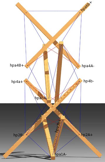
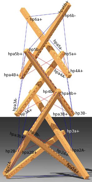
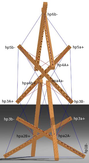
| Three Views of the Trellis/Plant Hanger | ||
structure file: chain/x2l4chain1b.rc variable file: chain/x2l4chain1b.dat stress-strain chart file: v02oct_s/evans.ssc cross-section table: chain/x2l4chain1b.cst digit list file: src/standard.dls |
CONTACT:
Bob Burkhardt
Tensegrity Solutions
Box 426164
Cambridge, MA 02142-0021
USA
e-mail: bobwb@juno.com