VRML model
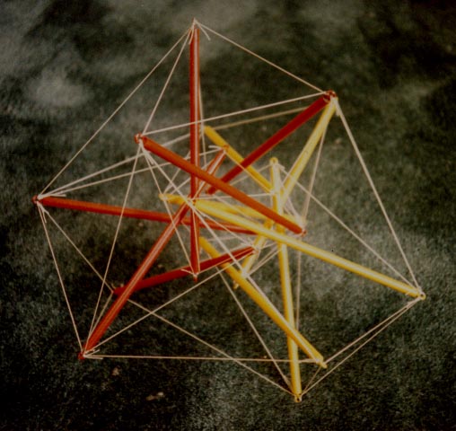
Due to its low frequency, this is the most extreme example of a double layer tensegrity. It is based on the 2ν breakdown of the octahedron. I put this together without the benefit of visualization software and considered (and still consider) myself lucky that the struts didn't come into conflict with each other or the tendons. The inner and outer layer both have the same tendon topology as Buckminster Fuller's tensegrity icosahedron (see the Jitterbug). It is remarkably rigid, especially in comparison with single layer tensegrities.
When I first started putting together these sorts of tensegrities I called them "laminar", a term I'd heard in conjunction with double-layer geodesic domes. Later, I found the term "double layer" in some civil engineering articles I read, so I decided to go with that term as more standard.
I completed assembling this figure on May 16, 1986. A less-successful earlier version with fewer tendons in the outer layer (it was like four four tensegrity tripods stuck around a core t-icosahedron tendon framework -- the four tendon triangles uniting the apexes of the tripods were not yet present) was assembled on July 21, 1982. I also assembled it at different scales and with different materials. A large outdoor version using 1" x 1" x 58" hardwood garden stakes for struts was completed April 2, 1998. It didn't exhibit the same rigidity, and the garden stakes warped terribly with the passage of time. A version using aluminum tubes for struts and stainless steel cable for tendons was assembled on December 3, 1993. It appears as Fig. Oct2v of my Tensegrity Technology prospectus. The steel tendons and gawky hubs prompted me to start including the hub geometry directly in the mathematical programming problems I was using to design the structure rather than relying on ad hoc adjustments. Now I think I could assemble it without the turnbuckles.
In parallel with this figure, I was also experimenting intensely with 4ν versions that got assembled November 22, 1985, June 5, 1986, June 17, 1988 and May 4, 1994. The last version is pictured as Fig. Oct4v of my Tensegrity Technology prospectus. The design of the 4ν structure is studied in depth in Section 5.3 of my book and a VRML model is also available.
The 4ν version exhibits the same rigidity. It also uses the full complement of interlayer tendons, that is two per strut. The 2ν figure only uses one interlayer tendon per strut, that being the tendon corresponding to the side tendon of the outward-pointing tensegrity tripods. It is possible to add the second set of interlayer tendons. At this low frequency, the so-called "inward-pointing" tripod actually points outward.


")