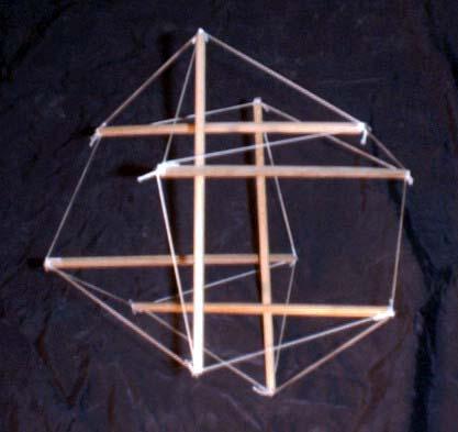
I designed this tensegrity vector equilibrium on June 30, 1981, the day after assembling the tower you saw in the previous photo. Hugh Kenner's exploration of tensegrity prisms in his book Geodesic Math and How to Use It (recently -- 2003 -- reissued by the University of California Press!) was the prime impetus.
On June 10 and 13, I had designed a tower based on the tensegrity prism. Although I wasn't too impressed with its structural performance, I did like that little trick of melding two prisms together. After some thought, I realized a tower like my first one with just one intermediate layer would have tendon edges which exactly coincided with a vector equilibrium (a.k.a. cuboctahedron), so I built that version whose photo you see above. As with my towers, some time later I found someone else, John Moelman in 1951, had had the same insight. See The Dymaxion World of Buckminster Fuller by R. Buckminster Fuller and Robert Marks, Figure 271.
For many years, this was the only model I had built that used tacks (small nails) in the ends instead of screw eyes to attach the tendons. The main advantage of this sort of hub for computing tendon lengths is that allowances don't have to be made for the space taken up by the hub. This is also the attachment method that Anthony Pugh recommends in Introduction to Tensegrity. For myself, I prefer screw eyes. The dowels in this model are 3/16 inches (4.75 mm) in diameter which is less than my usual 5/16 inches (8 mm). It also looks like I used a lighter grade (15 lb. test?) of braided-nylon fishing line than my usual (25 lb. test) which seems like a good idea with the thinner struts. As usual, I assumed the tendons stretched an average of 2%, an assumption I've always done well with, for fishing line anyway.
I took the above photo on December 25, 2003, after having this model for over 22 years. Despite its delicate appearance, it has been very resilient. After taking the photo I inadvertently laid into it with my bare foot with no ill effects to it. My foot tingled for awhile. This structure is available as "T-Cuboctahedron" in all the tensegrity viewers.
Also in my archives is another photo of a tensegrity vector equilibrium which must have been assembled around the same time. I can't find any notes for it so I don't know when it was made precisely, probably in 1981 sometime. Anthony Pugh's circuit pattern tensegrity cuboctahedron (An Introduction to Tensegrity, Fig. 4, p. 20) must have been an influence. A photo of my structure is below. I think the tendons must be made of wire fastened at either end by twisting.
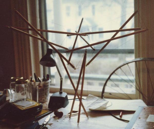
Cuboctahedron Supported by Four Tensegrity Three-Prisms
More recently, I found a group has been utilizing a tensegrity four-fold prism which coincides with the edges of a half cuboctahedron as a cell to construct tensegrity beams and planar trusses. See K. Kebiche, M. N. Kazi-Aoual and R. Motro, "Geometrical non-linear analysis of tensegrity systems", Engineering Structures, v. 21, no. 9 (Sep, 1999), pp. 864-876. After completing the datasheet, I built a model on April 11, 2005, using my more customary dowel-and-fishing-line technology. It is displayed in the photo below.
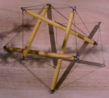
Half Cuboctahedron
(VRML Model)
Many years after building the tensegrity vector equilibrium, I returned to the modeling materials it uses to build the Skew Eight-Prism. I did a nicer job on the skew prism: its struts are painted.


