Figure 2.8: Tensegrity Tetrahedron
A Practical Guide to Tensegrity Design
Table of Contents
2.3 T-Icosahedron: A Diamond Tensegrity
2.4 T-Tetrahedron: A Zig-Zag Tensegrity
|
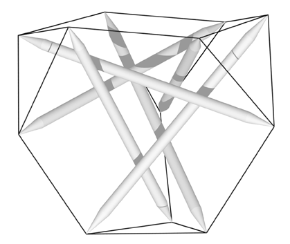
Figure 2.8: Tensegrity Tetrahedron |
The t-tetrahedron is illustrated in Figure 2.8. It was first exhibited by Francesco della Sala at the University of Michigan in 1952.17 It is called a "zig-zag" tensegrity because each strut is supported by two other struts tied into a zig-zag of three tendons spanning the strut. The t-tetrahedron is the zig-zag counterpart of the diamond t-icosahedron examined in Section 2.3. Both structures have six struts. The t-tetrahedron has four tendon triangles, whereas the t-icosahedron has eight.
Closer examination of these two structures yields another way the diamond and zig-zag forms can be contrasted. Four non-adjacent triangles of the t-icosahedron can be chosen to correspond to those of the t-tetrahedron. Each of these four triangles is connected to its three partners by two tendons (see Figure 2.4). For each pair of triangles, the "nose" of one is connected to the "ear" of the other (assuming the two triangles are looking at each other). This contrasts with the t-tetrahedron where each triangle is connected to each of its neighbors with a single tendon connecting the "noses" of the two triangles. With fewer tendons, the t-tetrahedron is simpler and less rigid than its diamond counterpart. In general, due to the use of fewer tendons, zig-zag structures are simpler and less rigid than their diamond counterparts.
The mathematical model for this structure is based on the structure itself and doesn't refer to any 3D coordinate systems. The mathematical analysis relies heavily on results from spherical trigonometry.18
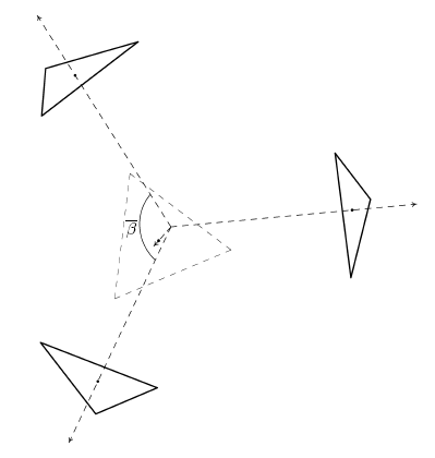 Figure 2.9: T-Tetrahedron: Mathematical Model |
Figure 2.9 illustrates the model for analyzing the t-tetrahedron. The t-tetrahedron can be conceived of as four triangles mounted on four rays extending from the center of the tetrahedron. The angle between any two of these rays is denoted by . The main interest here is in which is approximately (; ). Two of these rays and the corresponding triangles have been included in Figure 2.10.
All four triangles are symmetrical with respect to each other and have fixed radius . This symmetry allows only two methods of transforming a triangle: moving it in and out along its ray and rotating it about that ray. This symmetry also dictates that if one triangle rotates counter-clockwise,19 the other triangles rotate correspondingly. It is assumed that initially the triangles are oriented so they are all pointing at each other. The rotation angle is denoted by .
As mentioned, each pair of triangles is connected by a tendon (whose length is minimized) and a strut as well (whose length represents a constraint). It is assumed that the tendon runs between the two triangle vertices which are initially pointing at each other and that the strut runs between the two vertices () counter-clockwise from the vertices attached to the tendon.
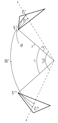 Figure 2.10: T-Tetrahedron: Mathematical Model (Detail) |
Since both triangles are orthogonal to their corresponding rays, all their vertices are the same distance from the center of the tetrahedron. This distance is denoted . Thus all the vertices can be conceived of as being located on a circumscribing sphere of radius . Two symmetrical instances of these vertices are labeled and . Other important points on this sphere are where the rays intersect it. These are labeled and .
The arc corresponding to the tendon (), the arc connecting the center points of the two triangles (), and the arcs corresponding to the radii of the two triangles ( and ) define two spherical triangles. These two triangles touch each other at the point where and intersect. This point is labeled . The symmetry of the structure dictates that the corresponding parts of these two triangles must be equal.20 This means that the arcs and are equal and their common measure is . Also
The angular measure of is denoted . It is useful to know how changes as a function of the twist angle and the sphere radius . This length can be computed using the Law of Cosines of Spherical Trigonometry. That law yields:
where denotes the arc length of which equals the arc length of . By inspection, it can be seen that and therefore so:
|
|
For convenience, the functional notation
denotes part of this expression. Note that only values which are variables in the analysis appear explicitly as arguments in this function.
From this cosine value, the length of the tendon connecting the two triangles (denoted ) and its second power can be derived as follows:
|
|
Again, for convenience the functional notation
is used. and refer to the partial derivatives of this function with respect to its first and second arguments.
|
|
Now only a formula for the strut length need be derived before the analysis moves on to the specification of the minimization problem. Strut length, denoted by , is specified by the formula:
This follows since, as noted above, the strut vertices are located radians counter-clockwise from the tendon vertices on the same two triangles.
So the minimization problem is simply:
Assuming the constraints can be solved for in terms of , this can be respecified as the unconstrained minimization problem:
The first-order condition for a minimum is:
.
An equation for is obtained by implicitly differentiating the constraint:
Substituting this expression into the original first-order condition yields:
.
This equation is solved simultaneously with the constraint equation to get the minimizing value of and incidentally the corresponding value for . While the mathematical programming problems examined in previous sections could be solved completely using mathematical formulas, this problem requires numerical tools to reach a final solution.
The procedure for numerically deriving a solution to these equations, and thus to the mathematical programming problem, is as follows:
| Step 1 | Set . |
| Step 2 | Given , solve the constraint for . |
| Step 3 | Given , solve the first-order condition for . |
| Step 4 | Repeat the process from Step 2 until converges. |
To find equation solutions, a simple binary algorithm for finding zeros of functions is used. This involves specifying a search interval for each equation21 and then evaluating the equation at each end point. One of the values should be greater than zero and one less than zero. The equation is then evaluated at the midpoint of the interval and a search interval specified which is bounded by the midpoint and the end point which differs from it in sign. In this manner, the search interval is halved at each iteration. When the search interval is less than twice the tolerance specified for a solution, the midpoint of the search interval is taken as the solution.
The fixed value for the triangle radius, , is chosen to be which implies a length of for the triangle tendons. The fixed strut length, , is chosen to be . Applying the above technique, the sequence of values shown in Table 2.3 is obtained.
| ||||||||||||||||||||||||
|
Table 2.3: T-Tetrahedron: Solution | ||||||||||||||||||||||||
The final solution was radians. The length of the tendon is obtained by substituting the final values for and into the equation for tendon length. This yields a tendon length of .
18 See Hogben65 pp. 367-382 for an intuitive look at spherical trigonometry, and Kells42, Chapters 3, 5 and 8 for a more thorough and technical look.
19 In speaking of triangle rotation, it is always assumed the structure is being viewed from outside. Counter-clockwise in this case amounts to a right-handed rotation of the triangle about its axis since the axis points out from the origin. From inside the structure, this would appear to be clockwise rotation.
20 In particular, the structure could be rotated , exchanging with , and the structure should appear to be unchanged.
21 For the constraint, and were used as the bounds for . For the first-order condition, and were used as the bounds for .
Table of Contents
2.5 Basic Tensegrity Structures: Conclusions