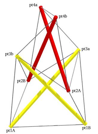
Two-Stage X-Module Column with Point Labels
        Member Descriptions
        [name, end point names, weight (if in objective function),
        second power of length (if a constraint), member category,
        Obj/Con/Exc (put in objective function, use as a constraint or
        exclude from computations), flags]
        For assembly purposes, only the name and end point names are
        of interest.  The other information may be of interest after
        A Practical Guide to Tensegrity Design has been consulted.

<Member> end1     pt4b  pt4a   0.0  sqr(1.24030)  3 Con *
<Member> end2     pt1A  pt1B   0.0  sqr(1.24030)  3 Con *

<Member> st13p    pt1A  pt3a   0.0  sqr(1.687248)  1 Con *
<Member> st24p    pt2A  pt4a   0.0  sqr(1.687248)  1 Con *

<Member> side2ap  pt2A  pt4b   1.0  0.0       3 Obj *
<Member> side2bp  pt4a  pt3a   1.0  0.0       3 Obj *

<Member> gird1ap  pt2A  pt3a   0.0  sqr(1.0)  2 Con *
<Member> gird1bp  pt2A  pt3b   0.0  sqr(1.0)  2 Con *

<Member> side1ap  pt1A  pt3b   1.0  0.0       3 Obj *
<Member> side1cp  pt1A  pt2B   1.0  0.0       3 Obj *

<Member> st13q    pt1B  pt3b   0.0  sqr(1.687248)  1 Con *
<Member> st24q    pt2B  pt4b   0.0  sqr(1.687248)  1 Con *

<Member> side2aq  pt2B  pt4a   1.0  0.0       3 Obj *
<Member> side2bq  pt4b  pt3b   1.0  0.0       3 Obj *

<Member> gird1aq  pt2B  pt3b   0.0  sqr(1.0)  2 Con *
<Member> gird1bq  pt2B  pt3a   0.0  sqr(1.0)  2 Con *

<Member> side1aq  pt1B  pt3a   1.0  0.0       3 Obj *
<Member> side1cq  pt1B  pt2A   1.0  0.0       3 Obj *


        In-Situ Member Lengths
        These are the lengths of the members when they are in place
        and prestress is applied.  The strut lengths are from
        screw-eye center to screw-eye center, as are the tendon lengths.
        These values are in model units.

     end1:       1.2403      end2:       1.2403     st13p:      1.68725
    st24p:      1.68725   side2ap:      1.21454   side2bp:     0.944266
  gird1ap:            1   gird1bp:            1   side1ap:      1.21454
  side1cp:     0.944266     st13q:      1.68725     st24q:      1.68725
  side2aq:      1.21454   side2bq:     0.944266   gird1aq:            1
  gird1bq:            1   side1aq:      1.21454   side1cq:     0.944266


        Relative Member Prestress Force Magnitudes
        These values are useful for developing an assembly
        strategy for the structure.  The tighter tendons are much
        easier to tie in place early on, while the looser tendons
        can be left to the last.  This information is also used
        to adjust tendon lengths since the measured length of a tendon
        will be shorter for a highly-stressed tendon with the same
        in-situ length as a tendon which is not so stressed.

     end1:      1.34293      end2:      1.34293     st13p:      -2.6076
    st24p:      -2.6076   side2ap:      1.21454   side2bp:     0.944266
  gird1ap:       1.2001   gird1bp:       1.2001   side1ap:      1.21454
  side1cp:     0.944266     st13q:      -2.6076     st24q:      -2.6076
  side2aq:      1.21454   side2bq:     0.944266   gird1aq:       1.2001
  gird1bq:       1.2001   side1aq:      1.21454   side1cq:     0.944266

        Average tendon force magnitude: 1.15154


        Construction Lengths (in millimeters and halves)
        The construction length of a tendon is less than the in-situ
        length since when the tendon is measured off it isn't under
        any prestress force.  The construction length for the strut
        represents the length of the 5/16-inch-diameter wooden dowel.
        Braided nylon fishing line was used for the tendons.
        Prestress forces are assumed to affect tendon lengths and
        not strut lengths.

        Elongation of Tendon of Unit Cross Section
        Under Force of Average Magnitude (fraction)> 0.02
        Length Scale Factor> 238/1.687248
        Strut and Tendon Hub Adjustments - s;t> 5.0 4.0
        (The 5.0 mm adjustment for the strut is the amount
         the screw-eye center extends from the dowel.  The 4.0 mm
	 adjustment for the tendon is half the outer diameter of the
         screw eye.)

     end1: 163 0      end2: 163 0     st13p: 228 0     st24p: 228 0
  side2ap: 160 0   side2bp: 123 0   gird1ap: 130 1   gird1bp: 130 1
  side1ap: 160 0   side1cp: 123 0     st13q: 228 0     st24q: 228 0
  side2aq: 160 0   side2bq: 123 0   gird1aq: 130 1   gird1bq: 130 1
  side1aq: 160 0   side1cq: 123 0
Two-Stage X-Module Column with Point Labels
structure file: chain/x2l2chain2.rc variable file: chain/x2l2chain2.dat digit list: ../src/mm.dls |
CONTACT:
Bob Burkhardt
Tensegrity Solutions
Box 426164
Cambridge, MA 02142-0021
USA
e-mail: bobwb@juno.com