Jan W. Marcus
Civil Engineer
Prinsesselaan 8 A
1942 AH Beverwijk
The Netherlands
E-mail:
info@janmarcus.nl
Tensegrities (tensional integrities) are structures which have only pure compressive and pure tensile elements while compressive elements do not touch each other directly but are interconnected solely by tensile elements. Consequently they exist only if there is sufficient pre-tension in the tensile elements (similar with the spokes in a bicycle wheel). A lot of shapes have been published, based on spatial forms such as the icosahedra. To go from Design to Constructing actual physical structures, there is a need for some kind of bridge. This bridge is the Analysis of stresses and displacements. For tensegrities, placed in the public domain or used as a structural component in some larger structures, these analysis are obviously critical essential. The problem with designing tensegrities is that the shape depends on the level of pre-tension and therefore those shapes cannot be stipulated easily. This presentation is about computer-programs, based on the Finite Element Method to do stress analysis on tensegrities. These programs can also be of great help to design tensegrities with a minimum of tensile components.
In a Dutch technical periodical [1] from the late sixties, there was an article concerning a marvelous tower of Kenneth Snelson. In the sculpture-garden of the Kröller-Müller museum in The Netherlands, his so-called "Needle Tower" was erected. This marvelous tower, about 18 meters high, was stable, but appeared to float in the air. It consisted of some thirty aluminum rods linked by some ninety cables.
A sentence in that article did not seem correct to me. Kenneth Snelson asserted that no engineer could analyze this tower. Concerning analysis, he meant the stresses and displacements of the structure. Of course, as a young civil engineer, I did not agree! At the company I worked for we had the computer program STRESS (STRuctural Engineering System Solver) available. At that moment, however, I had no time to do a test but from that moment I was interested in tensegrities. Years later, in the winter of 1978, I remembered this article. Of course, I could not find it anywhere, so I had to recreate the design of the tower on my own. I remembered that the tower consisted of only rods and cables, and the rods were not directly connected to each other.
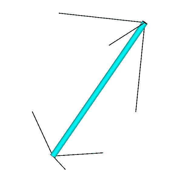
It is possible to erect a mast or stick using three cables; more are not needed, fewer is not possible. If you do not put the lower part of this mast or stick on the ground but use also three cables to lift it from the ground, the mast is stable in its surroundings; figure 1(a). By rotating this figure 0, 90 , 180 and 270 degrees around a vertical axis, then figure 1(b) arises. To prevent this structure from floating in the air, I put supports to the point 1, 2, 3 and 4; figure 1(c).
|
|
|
| (a) | (b) | (c) |
| Figure 1 | ||
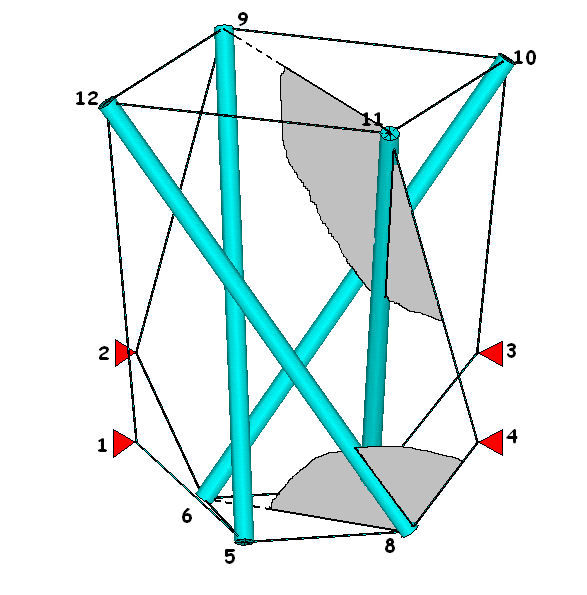
Now the rods are only connected to cables and they are stable in space! Of course the length of the rods and the cables cannot be chosen arbitrary. Because of axial symmetry, the tension forces in the cables of the horizontal squares are equal. So the resulting force, acting on the rods is in the diagonal direction. This tension force, the tension force in the third cable and the compression force in the rod must lie in one plane (plane 9-11-4-7) just like a clothesline between two walls with one stick in the middle. The same holds for the lower end of the rods (plane 6-8-4-12). With this data it is possible to determine the coordinates of all points.
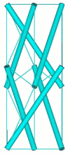
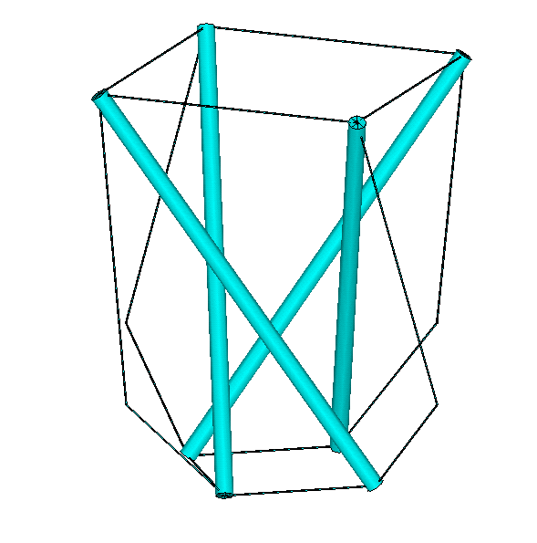
Now its possible to build a tower by stacking a number of these stories. But now the next problem arises: How to go from design (figure 2) to a real sculpture (figure 3). Or, what is the bridge between those two figures.
 |
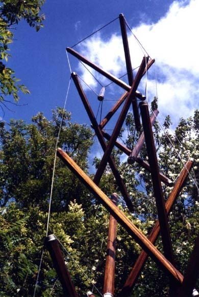 |
| Figure 2: Design | Figure 3: Sculpture |
To build save sculptures, it is necessary to use cables and rods that can withstand all the forces acting on the sculpture. So one must analyze the stresses and strains in all the elements. Not only for this 4.5 m high tower in my backyard (to prevent accidents with my grandchildren) but also for tensegrities, placed in the public domain (the large one at the Technical University Twente in The Netherlands) or used as a structural component (legs for a table). Probably, also the collapse of the Needle Tower during the storm of Sunday 27 October 2002 could be prevented.
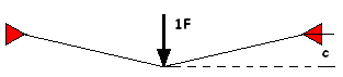
As a young stress engineer with the computer program STRESS available. (STRuctural Engineering System Solver, developed by the MIT to analyze stresses and displacements of plane and space trusses and frames) Unfortunately no results, other than the message ERRARE HUMANUM EST. The problem was the presence of mechanisms in the structure. To overcome these mechanisms pre-tensioning of the cables is required. But when pre-tensioning a structure, most of the time a geometric-non-linear solution is required. What is geometric-non-linearity? Let’s look at a simple problem. A cable long 130 cm, both ends fixed at a wall will be loaded in the middle with a vertical force. The cable has a cross section A=1 cm2 and a Young’s modulus E=1000 N/cm2.
 |
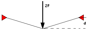 |
For a force F=15 N the deflection c=16.3 cm but for a force two times F the deflection d=20.7 cm and not two times 16.3 cm. This phenomenon is called “geometric-non-linearity”; it requires a lot of arithmetic. In the late seventies this approach came available in Finite Element Method programs like MSC/NASTRAN and ANSYS.
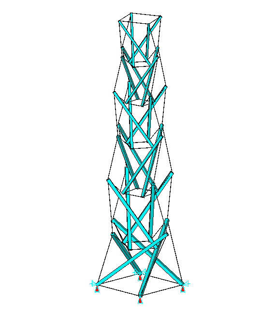
Now we have the BRIDGE to do an analysis of the tower. After choosing the dimensions of the wooden rods, the steel cables and the amount of shortening the cables to get them pre-tensioned, I prepared an input for MSC/NASTRAN. The results are shown in the next figures.
 |
 |
 |
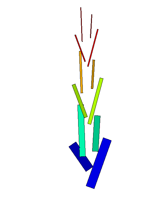
| (a) Analysis-model | (b) Compressive forces: -1144 to -79 N |
(c) Tensile stress: 20 to 195 N/mm2 |
| Figure 4 | ||
Figure 4(a) shows the supports at the four lower points. In figure 4(b) the compressive forces in the wooden rods are plotted and in figure 4(c) the tensile stress in the steel cables (all below the limits)
Because it is difficult to built the tower in this position, a second analysis is made with the same shortening of the cables and the tower in horizontal position. In this position the tower can easily be fabricated.
The cables must be connected to the upper and lower ends of the rods. Therefore I used cable clamps to connect the cables in caps. Because of the rods are always compressed, there is no need for gluing the caps at the rods. After all the cables are connected to caps, the rods can be denounced and after that the tower can be placed in an upright position. (In the presentation this will be shown in a reversed order).
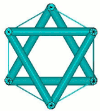
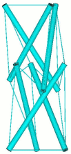
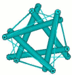
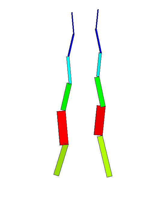
There are only a limited number of tensegrities possible, based on the previous principle with two times three cables connected to each rod. Instead of four rods for each story, one can use three, five or more rods. Always it looks like a stack of upside down cones (flowerpots). Instead of cones, I planned to use prismatic stories. To get the stories prismatic, it is not possible to do so with only three cables at the upper and three at the lower end of the rods. It is my intention to use as few cables as possible. Therefore I added to Anthony Pugh’s [2] definition of a tensegrity “a minimum number of tensile components” With the geometric-non-linear capabilities of today’s Finite Element Method programs, this must be possible. Starting with a stack of triangular prisms (figure 5) and pulling these prisms together by thin cables, a simple FEM-model can be made.
|
|
||||||||||||
By shortening only the thin cables in a non-linear analysis, the shape of such a model will be defined (figure 6). Of course it is, in top view not a nice Star of David as shown in figure 5 but we have found a shape with is far from a stack of cones and with a minimum number of cables. Now it’s possible to design a tower and do the same type of analysis as before.
For this tower I used aluminum tubes and nylon fishing wire. The wires (0.8 mm nylon) are fixed at the rods by means of small cable clamps on the wire and put in a slot at the end of the aluminum tubes (diameter 12 mm). The resulting tower, about 1.2 m high, agrees very well with the ANSYS results.
Today it is possible to analyze the stresses and displacements of tensegrities using the non-linear approaches of general purpose Finite Element Method computer programs. These programs can also be of great help in the design of tensegrities. Because the use of these programs requires a great deal of expertise, my advise is to become friends (build a BRIDGE) with a stress-engineer and construct together great tensegrities.
[1] DE INGENIEUR Jaargang 81 - nr.44 - 31 oktober 1969, page A 706 and A 707.
[2] “An Introduction to Tensegrity” by Anthony Pugh, University of California Press, 1976. ISBN 0-520-02996-8