<?xml version="1.0" encoding="iso-8859-1"?>
<!-- tenseg/book/chap2_2.xml  A Practical Guide to Tensegrity Design
     Copyright 2004-2008 Robert William Burkhardt, Jr. -->
<!DOCTYPE html PUBLIC "-//W3C//DTD XHTML 1.1 plus MathML 2.0//EN" 
          "http://www.w3.org/TR/MathML2/dtd/xhtml-math11-f.dtd"
          [<!ENTITY mathml "http://www.w3.org/1998/Math/MathML">]>
<html xmlns="http://www.w3.org/1999/xhtml" xml:lang="en">
<head>
<meta http-equiv="Content-Type" content="text/xhtml; charset=iso-8859-1"/>
<meta name="keywords"
      content="tensegrity, treatise, how-to, primer, thesis, basic, simple,
               mathematics, cylindrical coordinates, prism"/>
<meta name="description"
      content="A mathematical description of the tensegrity prism,
               a basic tensegrity structure."/>
<title>A Practical Guide to Tensegrity Design:
2.2&nbsp;T-Prism:  The Simplest Tensegrity</title>
<link rel="stylesheet" type="text/css" href="tenseg.css"/>
</head>

<body>
<p class="link">
A Practical Guide to Tensegrity Design<br/>
<a href="index.html#chap2_2">Table of Contents</a><br/>
2.1&nbsp;<a href="chap2_1.html">Basic Tensegrity Structures:  Introduction</a>
</p>

<p class="section-header-level1" id="tprism">
2.2&nbsp;T-Prism:  The Simplest Tensegrity
</p>

<p class="section-header-level2" id="tprism_intuition">
2.2.1&nbsp;T-Prism Intuition
</p>

<table id="fig_tprism" class="center"><tr align="center"><td>
<img src="tprism.png" width="229" height="432"
 alt="three sticks with eyes at both ends and tendons connecting them"/><br/>
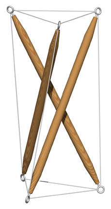
Figure 2.1:  Tensegrity Prism
</td></tr></table>

<p>
The t-prism is illustrated in
<a href="#fig_tprism">Figure&nbsp;2.1</a>.
It is the simplest and therefore one of the most
instructive members of the tensegrity family.
Some art historians believe it was first exhibited
by the Latvian artist Karl Ioganson
in Moscow in 1920-21 though this claim is
controversial.<sup><a href="#tx1" id="rf1">1</a></sup>
</p>

<p>
A model can be easily constructed using 5/16-inch-diameter (8&nbsp;mm) dowel,
some small screw eyes,<sup><a href="#tx2" id="rf2">2</a></sup>
and some braided
Dacron or nylon fishing line.  The dowel should be cut into three
seven-inch (178&nbsp;mm) lengths and an eye screwed into either end of each
length. 
Both eyes on a dowel should face the same direction. Then,
using the fishing line, the three dowels are tied together by
connecting one end of each of them to one end of each of the
others so that there is a three-inch (76&nbsp;mm) length of line between each
pair of dowels.<sup><a href="#tx3" id="rf3">3</a></sup>
The result should be an equilateral triangle of tendons, each three inches
(76&nbsp;mm) long, connecting the three struts together.
Next the opposite ends of the struts are tied together in a similar manner.
These two sets of tendons are the end tendons.
At this point, the result should be a triangular prism whose side edges
are marked out by the struts and whose triangular ends are made of fishing
lines (see <a href="#fig_tprism_nocoord">Figure 2.2</a>).
</p>

<table id="fig_tprism_nocoord" class="center"><tr align="center"><td>
<img src="tprism_nocoord.png" width="300" height="600"
 alt="three sticks with eyes at either end, ends connected by string"/><br/>
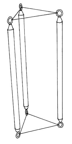
Figure 2.2:  T-Prism Construction:  Triangular Prism Stage
</td></tr></table>

<p>
The structure can be held up with a thumb and two fingers from each hand
so that it can be viewed as a prism.  When one end of the prism is twisted
relative to the other, the rectangular sides of the
prism lose their rectangularity and become non-planar
quadrilaterals.  Two opposite angles of each quadrilateral become
obtuse (greater than 90&deg;), and two opposite angles become
acute (less than 90&deg;).  The structure is completed
by connecting the vertices of each quadrilateral
corresponding to the two obtuse angles with
a tendon made of fishing line.
</p>

<p>
The length of these final three tendons
(one for each side of the prism -- the side tendons)
has to be chosen carefully;
otherwise, the structure will turn out to be a loose jumble of
sticks and fishing line.  As the two ends of
the prism are twisted relative to each other, the vertices
corresponding to the opposite obtuse angles initially grow closer to each
other.  As the twisting continues, there comes a point
where they start to move apart again. 
If the side tendons are tied with a length of fishing line which
corresponds to the minimum length reached at this
point,<sup><a href="#tx4" id="rf4">4</a></sup>
the structure is stable since it can't move away from
that configuration except by lengthening the distance between
those two points, and that is prevented by the minimum-length
tendon.  This is the "trick" which underlies all the tensegrity
design methods explored here.
</p>

<p>
So next the computation of the length of this
minimum-length tendon is explored.
</p>

<p class="section-header-level2" id="tprism_math_cyl">
2.2.2&nbsp;T-Prism Mathematics:  Cylindrical Coordinates
</p>

<p>
[A lot of the analysis presented in this section is derived from
<a href="refs.html#Kenner76"><i>Kenner76</i></a>, pp. 8-10.
The analysis presented there is a more general one.]
</p>

<table id="fig_tprism_cylcoord" class="center"><tr align="center"><td>
<img src="tprism_cylcoord.png" width="420" height="660"
 alt="three sticks with connecting string and coordinate system labeling"/>
<br/>
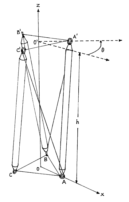
Figure 2.3:  T-Prism:  Cylindrical Coordinates
</td></tr></table>

<p>
For the t-prism, the most intuitive and convenient coordinate
system for mathematical analysis is the cylindrical coordinate
system.<sup><a href="#tx5" id="rf5">5</a></sup>
<a href="#fig_tprism_cylcoord">Figure&nbsp;2.3</a>
outlines how the t-prism is oriented in this
system.  The <math xmlns="&mathml;"><mi>z</mi></math> axis of the system coincides
with the axis of the t-prism
(<math xmlns="&mathml;">
 <mover accent="false"><mrow><mi>O</mi>
 <mo>&InvisibleTimes;</mo><mi>O</mi><mo>'</mo></mrow><mo>&OverBar;</mo>
 </mover></math>)
and therefore pierces the centers of the two
triangular ends.  The center of one of these ends
(<math xmlns="&mathml;"><mi>O</mi></math>) coincides
with the origin, while the other center
(<math xmlns="&mathml;"><mi>O</mi><mo>'</mo></math>) lies on the positive
<math xmlns="&mathml;"><mi>z</mi></math> axis.
The points which make up the triangle about the
origin are marked with the labels <math xmlns="&mathml;"><mi>A</mi></math>,
<math xmlns="&mathml;"><mi>B</mi></math>,
and <math xmlns="&mathml;"><mi>C</mi></math>.
The <math xmlns="&mathml;"><mi>z</mi></math> coordinate of all
these points is 0.  Their positions are held constant in the
mathematical analysis.  On the other triangle, the corresponding
points are marked
<math xmlns="&mathml;"><mi>A</mi><mo>'</mo></math>,
<math xmlns="&mathml;"><mi>B</mi><mo>'</mo></math> and
<math xmlns="&mathml;"><mi>C</mi><mo>'</mo></math>.
The <math xmlns="&mathml;"><mi>z</mi></math> coordinate of these
points is <math xmlns="&mathml;"><mi>h</mi></math>, the height of the t-prism.
This height is a variable in the mathematical analysis.  
</p>

<p>
Since the <math xmlns="&mathml;"><mi>z</mi></math>
axis goes through the centers of both triangles,
their vertices are equidistant from the
<math xmlns="&mathml;"><mi>z</mi></math> axis.  The measure of
this distance, denoted <math xmlns="&mathml;"><mi>r</mi></math>,
represents the radial portion of their
coordinate representation.  This value is also held constant
for the purposes of the mathematical analysis.  Besides the
<math xmlns="&mathml;"><mi>z</mi></math> axis,
the figure also contains the reference axis labeled
<math xmlns="&mathml;"><mi>x</mi></math>.
This axis serves as the reference for the value of the angular
coordinate.<sup><a href="#tx6" id="rf6">6</a></sup>
The value of this coordinate for
<math xmlns="&mathml;"><mi>A</mi><mo>'</mo></math> is the variable
<math xmlns="&mathml;"><mi>&theta;</mi></math>,
while the value of this coordinate for
<math xmlns="&mathml;"><mi>A</mi></math> is fixed at 0.  The
value of <math xmlns="&mathml;"><mi>&theta;</mi></math>
(which is measured in radians) measures the twist of
the two triangular ends with respect to each other.
Since <math xmlns="&mathml;"><mi>A</mi><mo>'</mo></math>,
<math xmlns="&mathml;"><mi>B</mi><mo>'</mo></math>,
and <math xmlns="&mathml;"><mi>C</mi><mo>'</mo></math>
lie on the same triangle, the angular component for
<math xmlns="&mathml;"><mi>B</mi><mo>'</mo></math> is
<math xmlns="&mathml;"><mrow>
  <mi>&theta;</mi><mo>+</mo>
  <mfrac>
    <mrow>
      <mi>2</mi><mo>&InvisibleTimes;</mo><mi>&pi;</mi>
    </mrow>
    <mi>3</mi>
  </mfrac>
</mrow></math> and that for
<math xmlns="&mathml;"><mi>C</mi><mo>'</mo></math> is
<math xmlns="&mathml;"><mrow>
  <mi>&theta;</mi><mo>-</mo>
  <mfrac>
    <mrow>
      <mi>2</mi><mo>&InvisibleTimes;</mo><mi>&pi;</mi>
    </mrow>
    <mi>3</mi>
  </mfrac>
</mrow></math>.
<a href="#tab_tppcoords">Table&nbsp;2.1</a> summarizes the coordinate values
for the six points.
</p>

<table id="tab_tppcoords" class="center"><tr><td align="center">
<table rules="groups" border="1">
<colgroup></colgroup>
<thead>
<tr><td></td><td colspan="3" align="center">Coordinates</td></tr>
<tr><td align="center">&nbsp;Point&nbsp;</td>
<td align="center">
&nbsp;&nbsp;<math xmlns="&mathml;"><mi>z</mi></math>&nbsp;&nbsp;</td>
<td align="center">radius</td>
<td align="center">angle</td>
</tr>
</thead>
<tbody>
<tr><td align="center"><math xmlns="&mathml;"><mi>A</mi></math></td>
<td align="center">0</td>
<td align="center"><math xmlns="&mathml;"><mi>r</mi></math></td>
<td align="center">0</td></tr>
<tr><td align="center"><math xmlns="&mathml;"><mi>B</mi></math></td>
<td align="center">0</td>
<td align="center"><math xmlns="&mathml;"><mi>r</mi></math></td>
<td align="center">
  <math xmlns="&mathml;"><mfrac>
    <mrow>
      <mi>2</mi><mo>&InvisibleTimes;</mo><mi>&pi;</mi>
    </mrow>
    <mi>3</mi>
  </mfrac></math>
</td></tr>
<tr><td align="center"><math xmlns="&mathml;"><mi>C</mi></math></td>
<td align="center">0</td>
<td align="center"><math xmlns="&mathml;"><mi>r</mi></math></td>
<td align="center">
  <math xmlns="&mathml;"><mo>-</mo><mfrac>
    <mrow>
      <mi>2</mi><mo>&InvisibleTimes;</mo><mi>&pi;</mi>
    </mrow>
    <mi>3</mi>
  </mfrac></math>
</td></tr>
</tbody><tbody>
<tr><td align="center">
<math xmlns="&mathml;"><mi>A</mi><mo>'</mo></math></td>
<td align="center"><math xmlns="&mathml;"><mi>h</mi></math></td>
<td align="center"><math xmlns="&mathml;"><mi>r</mi></math></td>
<td align="center"><math xmlns="&mathml;"><mi>&theta;</mi></math></td>
</tr>
<tr><td align="center">
<math xmlns="&mathml;"><mi>B</mi><mo>'</mo></math></td>
<td align="center"><math xmlns="&mathml;"><mi>h</mi></math></td>
<td align="center"><math xmlns="&mathml;"><mi>r</mi></math></td>
<td align="center">
<math xmlns="&mathml;"><mrow>
  <mi>&theta;</mi><mo>+</mo>
  <mfrac>
    <mrow>
      <mi>2</mi><mo>&InvisibleTimes;</mo><mi>&pi;</mi>
    </mrow>
    <mi>3</mi>
  </mfrac>
</mrow></math>
</td>
</tr>
<tr><td align="center">
<math xmlns="&mathml;"><mi>C</mi><mo>'</mo></math></td>
<td align="center"><math xmlns="&mathml;"><mi>h</mi></math></td>
<td align="center"><math xmlns="&mathml;"><mi>r</mi></math></td>
<td align="center">
<math xmlns="&mathml;"><mrow>
  <mi>&theta;</mi><mo>-</mo>
  <mfrac>
    <mrow>
      <mi>2</mi><mo>&InvisibleTimes;</mo><mi>&pi;</mi>
    </mrow>
    <mi>3</mi>
  </mfrac>
</mrow></math>
</td>
</tr>
</tbody>
</table>
</td></tr><tr><td align="center">
&nbsp;<br/>Table&nbsp;2.1:  T-Prism: Cylindrical Coordinates
</td></tr></table>

<p>
Now the struts, the compressive component of the
structure, can be inserted into the model.  These correspond to the line
segments
<math xmlns="&mathml;">
 <mover accent="false"><mrow><mi>A</mi>
 <mo>&InvisibleTimes;</mo><mi>A</mi><mo>'</mo></mrow><mo>&OverBar;</mo>
 </mover></math>,
<math xmlns="&mathml;">
 <mover accent="false"><mrow><mi>B</mi>
 <mo>&InvisibleTimes;</mo><mi>B</mi><mo>'</mo></mrow><mo>&OverBar;</mo>
 </mover></math> and
<math xmlns="&mathml;">
 <mover accent="false"><mrow><mi>C</mi>
 <mo>&InvisibleTimes;</mo><mi>C</mi><mo>'</mo></mrow><mo>&OverBar;</mo>
 </mover></math>.
Next, the side tendons are specified to link up the two tendon triangles
which make up the ends of the prism.  Starting from point
<math xmlns="&mathml;"><mi>A</mi></math>,
the side tendon can be connected to either
<math xmlns="&mathml;"><mi>B</mi><mo>'</mo></math> or
<math xmlns="&mathml;"><mi>C</mi><mo>'</mo></math>.
Either decision would result
in a viable structure provided the connections are made
consistently around the structure.  One of these structures would
be the mirror image of the other.  Here the side tendon is connected
to <math xmlns="&mathml;"><mi>C</mi><mo>'</mo></math>,
so the side tendons correspond to the line segments
<math xmlns="&mathml;">
 <mover accent="false"><mrow><mi>A</mi>
 <mo>&InvisibleTimes;</mo><mi>C</mi><mo>'</mo></mrow><mo>&OverBar;</mo>
</mover></math>,
<math xmlns="&mathml;">
 <mover accent="false"><mrow><mi>B</mi>
 <mo>&InvisibleTimes;</mo><mi>A</mi><mo>'</mo></mrow><mo>&OverBar;</mo>
</mover></math> and
<math xmlns="&mathml;">
 <mover accent="false"><mrow><mi>C</mi>
 <mo>&InvisibleTimes;</mo><mi>B</mi><mo>'</mo></mrow><mo>&OverBar;</mo>
</mover></math>.
</p>

<p>
Now the essence of the problem is reached:  how long should each
member (each tendon and each strut) be?  By fixing the
value of <math xmlns="&mathml;"><mi>r</mi></math>
(the radius of the prism's triangular ends), the length
of each end tendon (call this value
<math xmlns="&mathml;"><mi>u</mi></math>) has been fixed via the equation
<math xmlns="&mathml;"><mrow><mi>u</mi><mo>=</mo>
<mi>2</mi><mo>&InvisibleTimes;</mo>
<mi>r</mi><mo>sin</mo><mfrac><mi>&pi;</mi><mi>3</mi></mfrac></mrow></math>.
For the other members, there are
two choices.  The side tendon lengths,
<math xmlns="&mathml;">
 <mfenced open="|" close="|">
 <mover accent="false"><mrow><mi>A</mi>
 <mo>&InvisibleTimes;</mo><mi>C</mi><mo>'</mo></mrow><mo>&OverBar;</mo>
 </mover></mfenced></math>
etc., can be fixed and then
<math xmlns="&mathml;">
 <mover accent="false"><mrow><mi>A</mi>
 <mo>&InvisibleTimes;</mo><mi>A</mi><mo>'</mo></mrow><mo>&OverBar;</mo>
 </mover></math>
etc. chosen to be the <b>maximum</b>-length struts
compatible with these fixed tendon lengths; or, the strut lengths,
<math xmlns="&mathml;">
 <mfenced open="|" close="|">
 <mover accent="false"><mrow><mi>A</mi>
 <mo>&InvisibleTimes;</mo><mi>A</mi><mo>'</mo></mrow><mo>&OverBar;</mo>
 </mover></mfenced></math>
etc., can be fixed and then
<math xmlns="&mathml;">
 <mover accent="false"><mrow><mi>A</mi>
 <mo>&InvisibleTimes;</mo><mi>C</mi><mo>'</mo></mrow><mo>&OverBar;</mo>
 </mover></math>
etc. chosen to be the <b>minimum</b>-length
side tendons compatible with these fixed strut lengths.  Here,
the second procedure is used.<sup><a href="#tx7" id="rf7">7</a></sup>
The choice is arbitrary, and, in this case, there is no real benefit to
doing it one way or the other.  In more complex structures,
however, fixing the strut lengths
<i>a priori</i> allows the designer to specify
them all to be equal.  This uniformity eases the
manufacture of the struts since only one length of strut needs to
be made.
</p>

<p>
So the problem is:
</p>

<p>
Using the variables <math xmlns="&mathml;"><mi>h</mi></math> and
<math xmlns="&mathml;"><mi>&theta;</mi></math>, minimize
side tendon length
<math xmlns="&mathml;"><mrow>
 <mi>t</mi><mo>=</mo>
 <mfenced open="|" close="|"><mover accent="false"><mrow><mi>A</mi>
 <mo>&InvisibleTimes;</mo><mi>C</mi><mo>'</mo></mrow><mo>&OverBar;</mo>
 </mover></mfenced></mrow></math>
keeping in mind the following constraints:
</p>

<ul>
<li>Fixed triangle radius
<math xmlns="&mathml;">
 <mover><mi>r</mi><mo>&OverBar;</mo></mover>
</math></li>
<li>Fixed strut length
<math xmlns="&mathml;"><mrow>
 <mover><mi>s</mi><mo>&OverBar;</mo></mover><mo>=</mo><mi>s</mi><mo>=</mo>
 <mfenced open="|" close="|"><mover accent="false"><mrow><mi>A</mi>
 <mo>&InvisibleTimes;</mo><mi>A</mi><mo>'</mo></mrow><mo>&OverBar;</mo>
 </mover></mfenced>
</mrow></math></li>
<li>Strut symmetry constraints:
<math xmlns="&mathml;"><mrow>
 <mfenced open="|" close="|"><mover accent="false"><mrow><mi>A</mi>
 <mo>&InvisibleTimes;</mo><mi>A</mi><mo>'</mo></mrow><mo>&OverBar;</mo>
 </mover></mfenced><mo>=</mo>
 <mfenced open="|" close="|"><mover accent="false"><mrow><mi>B</mi>
 <mo>&InvisibleTimes;</mo><mi>B</mi><mo>'</mo></mrow><mo>&OverBar;</mo>
 </mover></mfenced><mo>=</mo>
 <mfenced open="|" close="|"><mover accent="false"><mrow><mi>C</mi>
 <mo>&InvisibleTimes;</mo><mi>C</mi><mo>'</mo></mrow><mo>&OverBar;</mo>
 </mover></mfenced></mrow></math></li>
<li>Side-tendon symmetry constraints:
<math xmlns="&mathml;"><mrow>
 <mfenced open="|" close="|"><mover accent="false"><mrow><mi>A</mi>
 <mo>&InvisibleTimes;</mo><mi>C</mi><mo>'</mo></mrow><mo>&OverBar;</mo>
 </mover></mfenced><mo>=</mo>
 <mfenced open="|" close="|"><mover accent="false"><mrow><mi>B</mi>
 <mo>&InvisibleTimes;</mo><mi>A</mi><mo>'</mo></mrow><mo>&OverBar;</mo>
 </mover></mfenced><mo>=</mo>
 <mfenced open="|" close="|"><mover accent="false"><mrow><mi>C</mi>
 <mo>&InvisibleTimes;</mo><mi>B</mi><mo>'</mo></mrow><mo>&OverBar;</mo>
 </mover></mfenced></mrow></math></li>
</ul>

<p>
The symmetry constraints stem from the fact that this tensegrity
is based on a triangular prism which exhibits three-fold symmetry
about its axis.  Symmetrical struts are chosen to be of equal length for
convenience.  They could just as well be specified to all have
different lengths.  The side tendon lengths are chosen to be equal for
convenience also.  Here more care needs to be taken since
the side tendon lengths,
<math xmlns="&mathml;">
 <mfenced open="|" close="|"><mover accent="false"><mrow><mi>A</mi>
 <mo>&InvisibleTimes;</mo><mi>C</mi><mo>'</mo></mrow><mo>&OverBar;</mo>
 </mover></mfenced>
</math> etc.,
are variables of the problem, and
artificial constraints here could invalidate the mathematical
model of the structure.  There is nothing in the geometry of the
structure which says these tendons must be equal, and actually,
even with all the strut lengths equal,
a valid structure could be constructed with these tendons unequal in length;
but, as it turns out, when the structure otherwise exhibits a
rotational symmetry, imposing this symmetry on the solution
results in a viable structure, and, as important, it whittles
down the size of the problem considerably.
</p>

<p>
To get mathematical formulas for the different lengths,
the formula for the length of a chord on a cylinder is needed.
It is:
</p>

<p class="center">
<math xmlns="&mathml;"><mrow><msup><mi>l</mi><mn>2</mn></msup><mo>=</mo>
<msup><mfenced><mrow><mo>&Delta;</mo><mi>z</mi></mrow></mfenced>
<mn>2</mn></msup><mo>+</mo>
<msup><mrow><mn>2</mn><mi>r</mi></mrow><mn>2</mn></msup><mo>-</mo>
<mrow><msup><mrow><mn>2</mn><mi>r</mi></mrow><mn>2</mn></msup>
<mo>&InvisibleTimes;</mo><mo>cos</mo>
<mfenced><mrow><mo>&Delta;</mo><mi>&theta;</mi></mrow></mfenced>
</mrow></mrow></math>
</p>

<p>
where:
</p>

<table class="center"><tr><td>
<math xmlns="&mathml;"><mrow><mi>l</mi><mo>=</mo>
<mtext>length of the chord</mtext></mrow></math><br/>
<math xmlns="&mathml;"><mrow><mrow><mo>&Delta;</mo><mi>z</mi></mrow><mo>=</mo>
<mtext>difference in z coordinate between the two points
</mtext></mrow></math><br/>
<math xmlns="&mathml;"><mrow><mi>r</mi><mo>=</mo>
<mtext>radius of the cylinder</mtext></mrow></math><br/>
<math xmlns="&mathml;"><mrow><mrow><mo>&Delta;</mo><mi>&theta;</mi></mrow>
<mo>=</mo>
<mtext>difference in angular coordinate between the two points
</mtext></mrow></math>
</td></tr></table>

<p>
Notice that the formula is expressed in terms of the second power
of the length.  The second root of this expression
would also yield a formula for the length; but, it is just as
valid,<sup><a href="#tx8" id="rf8">8</a></sup>
and, more importantly, mathematically easier, to work in second
powers.  In virtually every tensegrity problem examined in these
notes, working with second powers of lengths makes
the problem more tractable.
</p>

<p>
All this considered, the final mathematical form for the problem
is:
</p>

<p class="center">
<math xmlns="&mathml;"><mtable>
<mtr><mtd><mtext>minimize</mtext></mtd>
<mtd>
 <mrow><msup><mi>t</mi><mn>2</mn></msup><mo>=</mo>
 <msup><mfenced open="|" close="|"><mover accent="false"><mrow><mi>A</mi>
 <mo>&InvisibleTimes;</mo><mi>C</mi><mo>'</mo></mrow><mo>&OverBar;</mo>
 </mover></mfenced><mn>2</mn></msup><mo>=</mo><msup><mi>h</mi><mn>2</mn></msup>
 <mo>+</mo><mn>2</mn><mo>&InvisibleTimes;</mo>
 <msup><mi>r</mi><mn>2</mn></msup>
 <mo>-</mo><mrow><mn>2</mn><mo>&InvisibleTimes;</mo>
 <msup><mi>r</mi><mn>2</mn></msup><mo>&InvisibleTimes;</mo>
 <mo>cos</mo><mfenced><mrow><mfrac><mrow><mn>2</mn><mn>&pi;</mn></mrow>
 <mn>3</mn></mfrac><mo>-</mo><mi>&theta;</mi></mrow></mfenced></mrow></mrow>
 </mtd></mtr>

 <mtr><mtd><mrow><mi>&theta;</mi><mo>,</mo><mi>h</mi></mrow></mtd></mtr>
 <mtr><mtd></mtd></mtr>
 <mtr><mtd><mtext>subject to</mtext></mtd>
 <mtd><mrow>
 <msup><mover><mi>s</mi><mo>&OverBar;</mo></mover><mn>2</mn></msup>
 <mo>=</mo><msup><mi>s</mi><mn>2</mn></msup><mo>=</mo>
 <msup><mfenced open="|" close="|"><mover accent="false"><mrow><mi>A</mi>
 <mo>&InvisibleTimes;</mo><mi>A</mi><mo>'</mo></mrow><mo>&OverBar;</mo>
 </mover></mfenced><mn>2</mn></msup><mo>=</mo>
 <msup><mi>h</mi><mn>2</mn></msup><mo>+</mo><mn>2</mn>
 <mo>&InvisibleTimes;</mo><msup><mi>r</mi><mn>2</mn></msup><mo>-</mo>
 <mn>2</mn>
 <mo>&InvisibleTimes;</mo><msup><mi>r</mi><mn>2</mn></msup>
 <mo>&InvisibleTimes;</mo><mo>cos</mo><mi>&theta;</mi></mrow></mtd></mtr>
 <mtr><mtd></mtd><mtd><mrow>
 <mover><mi>r</mi><mo>&OverBar;</mo></mover><mo>=</mo><mi>r</mi>
 </mrow></mtd></mtr>
</mtable>
</math>
</p>

<p>
This constrained optimization problem can be turned into an easier
unconstrained one by solving the constraint for
<math xmlns="&mathml;"><mrow><msup><mi>h</mi><mn>2</mn></msup><mo>+</mo>
<mn>2</mn><mo>&InvisibleTimes;</mo><msup><mi>r</mi><mn>2</mn></msup></mrow>
</math>
and substituting this into the objective function.  Doing this,
the equivalent unconstrained problem is obtained:
</p>

<p class="center">
<math xmlns="&mathml;"><mtable>
<mtr><mtd><mtext>minimize</mtext></mtd>
<mtd>
 <mrow>
 <msup><mover><mi>s</mi><mo>&OverBar;</mo></mover><mn>2</mn></msup>
 <mo>+</mo><mn>2</mn><mo>&InvisibleTimes;</mo>
 <msup><mover><mi>r</mi><mo>&OverBar;</mo></mover><mn>2</mn></msup>
 <mo>&InvisibleTimes;</mo>
 <mo>cos</mo><mi>&theta;</mi><mo>-</mo>
 <mn>2</mn><mo>&InvisibleTimes;</mo>
 <msup><mover><mi>r</mi><mo>&OverBar;</mo></mover><mn>2</mn></msup>
 <mo>&InvisibleTimes;</mo>
 <mo>cos</mo><mfenced><mrow><mfrac><mrow><mn>2</mn><mn>&pi;</mn></mrow>
 <mn>3</mn></mfrac><mo>-</mo><mi>&theta;</mi></mrow></mfenced></mrow>
 </mtd></mtr>
 <mtr><mtd><mi>&theta;</mi></mtd></mtr>
 </mtable></math>
</p>

<p>
Taking the derivative with respect to
<math xmlns="&mathml;"><mi>&theta;</mi></math>
and equating the result to 0
yields:<sup><a href="#tx9" id="rf9">9</a></sup>
</p>

<p class="center">
<math xmlns="&mathml;">
 <mrow>
 <mo>-</mo><mn>2</mn><mo>&InvisibleTimes;</mo>
 <msup><mover><mi>r</mi><mo>&OverBar;</mo></mover><mn>2</mn></msup>
 <mo>&InvisibleTimes;</mo>
 <mo>sin</mo><mi>&theta;</mi><mo>-</mo>
 <mn>2</mn><mo>&InvisibleTimes;</mo>
 <msup><mover><mi>r</mi><mo>&OverBar;</mo></mover><mn>2</mn></msup>
 <mo>&InvisibleTimes;</mo>
 <mo>sin</mo><mfenced><mrow><mfrac><mrow><mn>2</mn><mn>&pi;</mn></mrow>
 <mn>3</mn></mfrac><mo>-</mo><mi>&theta;</mi></mrow></mfenced><mo>=</mo>
 <mn>0</mn></mrow>
</math>
</p>

<p>
or
</p>

<p class="center">
<math xmlns="&mathml;">
 <mrow>
 <mo>sin</mo><mi>&theta;</mi><mo>=</mo>
 <mo>-</mo>
 <mo>sin</mo><mfenced><mrow><mfrac><mrow><mn>2</mn><mn>&pi;</mn></mrow>
 <mn>3</mn></mfrac><mo>-</mo><mi>&theta;</mi></mrow></mfenced><mo>=</mo>
 <mo>sin</mo><mfenced><mrow><mi>&theta;</mi><mo>-</mo>
 <mfrac><mrow><mn>2</mn><mn>&pi;</mn></mrow>
 <mn>3</mn></mfrac></mrow></mfenced>
 </mrow>
</math>
</p>

<p>
The sines of two angles can be equal only if
either their <b>difference</b> is an <b>even</b> multiple of
<math xmlns="&mathml;"><mn>&pi;</mn></math>,
or their <b>sum</b> is an <b>odd</b> multiple of
<math xmlns="&mathml;"><mn>&pi;</mn></math>.
In this case only the latter is a
possibility.<sup><a href="#tx10" id="rf10">10</a></sup>
</p>

<p>
The first alternative is that that the sum is just
<math xmlns="&mathml;"><mn>&pi;</mn></math>,
i.e. that:
</p>

<p class="center">
<math xmlns="&mathml;">
 <mrow><mi>&theta;</mi><mo>+</mo>
 <mfenced><mrow><mi>&theta;</mi><mo>-</mo>
 <mfrac><mrow><mn>2</mn><mn>&pi;</mn></mrow>
 <mn>3</mn></mfrac></mrow></mfenced>
 <mo>=</mo><mn>&pi;</mn>
 </mrow>
</math>
</p>

<p>
which means a solution to the problem is
</p>

<p class="center">
<math xmlns="&mathml;">
<mrow>
 <mi>&theta;</mi><mo>=</mo>
 <mfrac><mrow><mn>5</mn><mo>&InvisibleTimes;</mo><mn>&pi;</mn></mrow>
 <mn>6</mn></mfrac><mo>=</mo><mn>150&deg;</mn>
</mrow></math>.
</p>

<p>
Substitution of this value for
<math xmlns="&mathml;"><mi>&theta;</mi></math>
into the modified objective function above yields:
</p>

<p class="center">
<math xmlns="&mathml;"><mrow>
 <msup><mi>t</mi><mn>2</mn></msup><mo>=</mo> 
 <msup><mfenced open="|" close="|"><mover accent="false"><mrow><mi>A</mi>
 <mo>&InvisibleTimes;</mo><mi>C</mi><mo>'</mo></mrow><mo>&OverBar;</mo>
 </mover></mfenced><mn>2</mn></msup><mo>=</mo>
 <msup><mover><mi>s</mi><mo>&OverBar;</mo></mover><mn>2</mn></msup>
 <mo>+</mo><mn>2</mn><mo>&InvisibleTimes;</mo>
 <msup><mover><mi>r</mi><mo>&OverBar;</mo></mover><mn>2</mn></msup>
 <mo>&InvisibleTimes;</mo>
 <mo>cos</mo><mfenced><mfrac>
 <mrow><mn>5</mn><mo>&InvisibleTimes;</mo><mn>&pi;</mn></mrow>
 <mn>6</mn></mfrac></mfenced>
 <mo>-</mo><mn>2</mn><mo>&InvisibleTimes;</mo>
 <msup><mover><mi>r</mi><mo>&OverBar;</mo></mover><mn>2</mn></msup>
 <mo>&InvisibleTimes;</mo>
 <mo>cos</mo><mfenced><mfrac>
 <mrow><mo>-</mo><mn>&pi;</mn></mrow>
 <mn>6</mn></mfrac></mfenced>
 </mrow></math>.
</p>

<p>
In the experiment above, the fixed strut length,
<math xmlns="&mathml;"><mover><mi>s</mi><mo>&OverBar;</mo></mover></math>,
was <math xmlns="&mathml;"><mn>7</mn></math> and the fixed end tendon length,
<math xmlns="&mathml;"><mover><mi>u</mi><mo>&OverBar;</mo></mover></math>,
was <math xmlns="&mathml;"><mn>3</mn></math>.  Hence:
</p>

<p class="center">
<math xmlns="&mathml;">
<mtable><mtr><mtd>
<mrow><msup><mover><mi>s</mi><mo>&OverBar;</mo></mover><mn>2</mn></msup>
<mo>=</mo><msup><mn>7</mn><mn>2</mn></msup><mo>=</mo><mn>49</mn></mrow>
</mtd></mtr>
<mtr><mtd>
<mrow><msup><mover><mi>r</mi><mo>&OverBar;</mo></mover><mn>2</mn></msup>
<mo>=</mo><msup><mfenced><mfrac><mover><mi>u</mi><mo>&OverBar;</mo></mover>
<mrow><mn>2</mn><mo>&InvisibleTimes;</mo><mo>sin</mo>
<mfenced><mfrac><mn>&pi;</mn><mn>3</mn></mfrac></mfenced></mrow>
</mfrac></mfenced><mn>2</mn></msup>
<mo>=</mo><msup><mfenced><mfrac><mn>3</mn>
<mrow><mn>2</mn><mo>&InvisibleTimes;</mo><mo>sin</mo>
<mfenced><mfrac><mn>&pi;</mn><mn>3</mn></mfrac></mfenced></mrow>
</mfrac></mfenced><mn>2</mn></msup>
<mo>=</mo><mn>3</mn></mrow>
</mtd></mtr></mtable>
</math>
</p>

<p>
and therefore:
</p>

<p class="center">
<math xmlns="&mathml;"><mrow>
 <msup><mi>t</mi><mn>2</mn></msup><mo>=</mo>
 <msup><mfenced open="|" close="|"><mover accent="false"><mrow><mi>A</mi>
 <mo>&InvisibleTimes;</mo><mi>C</mi><mo>'</mo></mrow><mo>&OverBar;</mo>
 </mover></mfenced><mn>2</mn></msup><mo>=</mo>
 <mn>49</mn><mo>+</mo><mn>2</mn><mo>&sdot;</mo><mn>3</mn>
 <mo>&InvisibleTimes;</mo><mfenced><mrow>
 <mfrac><mrow><mo>-</mo><msqrt><mn>3</mn></msqrt></mrow><mn>2</mn></mfrac>
 <mo>-</mo><mfrac><msqrt><mn>3</mn></msqrt><mn>2</mn></mfrac>
 </mrow></mfenced>
 <mo>=</mo><mn>49</mn><mo>-</mo><mn>2</mn><mo>&sdot;</mo><mn>3</mn>
 <mo>&InvisibleTimes;</mo><msqrt><mn>3</mn></msqrt>
 <mo>=</mo><mn>38.6077</mn>
 </mrow></math>
</p>

<p>
So
<math xmlns="&mathml;"><mrow>
 <mi>t</mi><mo>=</mo><mfenced open="|" close="|"><mover accent="false">
 <mrow><mi>A</mi><mo>&InvisibleTimes;</mo><mi>C</mi><mo>'</mo></mrow>
 <mo>&OverBar;</mo>
</mover></mfenced></mrow></math> = 6.2135 inches (158&nbsp;mm).
</p>

<p>
The next alternative is that the sum is
<math xmlns="&mathml;"><mo>-</mo><mn>&pi;</mn></math>,
i.e. that
</p>

<p class="center">
<math xmlns="&mathml;">
 <mrow><mi>&theta;</mi><mo>+</mo>
 <mfenced><mrow><mi>&theta;</mi><mo>-</mo>
 <mfrac><mrow><mn>2</mn><mn>&pi;</mn></mrow>
 <mn>3</mn></mfrac></mrow></mfenced>
 <mo>=</mo><mo>-</mo><mn>&pi;</mn>
 </mrow>
</math>
</p>

<p>
This alternative yields the solution
</p>

<p class="center">
<math xmlns="&mathml;">
<mrow>
 <mi>&theta;</mi><mo>=</mo>
 <mfrac><mrow><mo>-</mo><mn>&pi;</mn></mrow>
 <mn>6</mn></mfrac>
</mrow></math>.
</p>

<p>
This solution corresponds to a <b>maximum</b> value of the objective
function rather than a minimum. 
Mathematically, this alternative could be eliminated by examining the
second-order conditions for a minimum.  The previous solution
would fulfill them; this solution would not.  For now, such care need not
be taken since it is also known that
<math xmlns="&mathml;"><mi>&theta;</mi></math>
needs to be positive.  However, as the models get more complex,
these issues need to be dealt with.
This latter solution <b>would</b> be a valid tensegrity solution if
the strut length were being maximized with respect to a
fixed-length side tendon.
</p>

<p>
All other alternatives<sup><a href="#tx11" id="rf11">11</a></sup>
are equivalent to the two
examined since the other alternatives can be reduced to one of
the solutions examined plus an even multiple of
<math xmlns="&mathml;"><mn>&pi;</mn></math>.
</p>

<p class="section-header-level2" id="tprism_math_car">
2.2.3&nbsp;T-Prism Mathematics:  Cartesian Coordinates
</p>

<p>
As an introduction to the material presented in succeeding chapters,
the triangular t-prism is re-examined from the vantage point of
Cartesian coordinates.  The three-fold symmetry of the triangular
prism make this analysis much simpler as compared
with prisms of higher symmetry.
</p>

<p>
Now each vertex of the prism is expressed as a point in
<math xmlns="&mathml;">
<mi>x</mi><mo>&InvisibleTimes;</mo><mi>y</mi>
<mo>&InvisibleTimes;</mo><mi>z</mi></math>-space.
The three-fold symmetry constrains the coordinates
of the three points within each triangle to be permutations of
each other.  <math xmlns="&mathml;"><mi>A</mi></math> and
<math xmlns="&mathml;"><mi>A</mi><mo>'</mo></math>
are arbitrarily chosen to be the basic points.
The other points are called symmetry points since they are
generated from the basic points via symmetry transformations,
permutations in this case.  These coordinate values are
summarized in <a href="#tab_tpccoords">Table&nbsp;2.2</a> and illustrated in
<a href="#fig_tprism_carcoord">Figure&nbsp;2.4</a>.
</p>

<table id="tab_tpccoords" class="center"><tr><td align="center">
<table rules="groups" border="1">
<colgroup></colgroup>
<thead>
<tr><td></td><td colspan="3" align="center">Coordinates</td></tr>
<tr><td align="center">&nbsp;Point&nbsp;</td>
<td align="center">
&nbsp;&nbsp;<math xmlns="&mathml;"><mi>x</mi></math>&nbsp;&nbsp;</td>
<td align="center">
&nbsp;&nbsp;<math xmlns="&mathml;"><mi>y</mi></math>&nbsp;&nbsp;</td>
<td align="center">
&nbsp;&nbsp;<math xmlns="&mathml;"><mi>z</mi></math>&nbsp;&nbsp;</td>
</tr>
</thead>
<tbody>
<tr><td align="center"><math xmlns="&mathml;"><mi>A</mi></math></td>
<td align="center">
&nbsp;&nbsp;<math xmlns="&mathml;"><msub><mi>x</mi><mi>A</mi></msub></math>&nbsp;&nbsp;</td>
<td align="center">
&nbsp;&nbsp;<math xmlns="&mathml;"><msub><mi>y</mi><mi>A</mi></msub></math>&nbsp;&nbsp;</td>
<td align="center">
&nbsp;&nbsp;<math xmlns="&mathml;"><msub><mi>z</mi><mi>A</mi></msub></math>&nbsp;&nbsp;</td></tr>
<tr><td align="center"><math xmlns="&mathml;"><mi>B</mi></math></td>
<td align="center">
&nbsp;&nbsp;<math xmlns="&mathml;"><msub><mi>z</mi><mi>A</mi></msub></math>&nbsp;&nbsp;</td>
<td align="center">
&nbsp;&nbsp;<math xmlns="&mathml;"><msub><mi>x</mi><mi>A</mi></msub></math>&nbsp;&nbsp;</td>
<td align="center">
&nbsp;&nbsp;<math xmlns="&mathml;"><msub><mi>y</mi><mi>A</mi></msub></math>&nbsp;&nbsp;</td></tr>
<tr><td align="center"><math xmlns="&mathml;"><mi>C</mi></math></td>
<td align="center">
&nbsp;&nbsp;<math xmlns="&mathml;"><msub><mi>y</mi><mi>A</mi></msub></math>&nbsp;&nbsp;</td>
<td align="center">
&nbsp;&nbsp;<math xmlns="&mathml;"><msub><mi>z</mi><mi>A</mi></msub></math>&nbsp;&nbsp;</td>
<td align="center">
&nbsp;&nbsp;<math xmlns="&mathml;"><msub><mi>x</mi><mi>A</mi></msub></math>&nbsp;&nbsp;</td></tr>
</tbody><tbody>
<tr><td align="center">
<math xmlns="&mathml;"><mi>A</mi><mo>'</mo></math></td>
<td align="center">
&nbsp;&nbsp;<math xmlns="&mathml;"><msub><mi>x</mi><mrow><mi>A</mi><mo>'</mo></mrow></msub></math>&nbsp;&nbsp;</td>
<td align="center">
&nbsp;&nbsp;<math xmlns="&mathml;"><msub><mi>y</mi><mrow><mi>A</mi><mo>'</mo></mrow></msub></math>&nbsp;&nbsp;</td>
<td align="center">
&nbsp;&nbsp;<math xmlns="&mathml;"><msub><mi>z</mi><mrow><mi>A</mi><mo>'</mo></mrow></msub></math>&nbsp;&nbsp;</td>
</tr>
<tr><td align="center">
<math xmlns="&mathml;"><mi>B</mi><mo>'</mo></math></td>
<td align="center">
&nbsp;&nbsp;<math xmlns="&mathml;"><msub><mi>z</mi><mrow><mi>A</mi><mo>'</mo></mrow></msub></math>&nbsp;&nbsp;</td>
<td align="center">
&nbsp;&nbsp;<math xmlns="&mathml;"><msub><mi>x</mi><mrow><mi>A</mi><mo>'</mo></mrow></msub></math>&nbsp;&nbsp;</td>
<td align="center">
&nbsp;&nbsp;<math xmlns="&mathml;"><msub><mi>y</mi><mrow><mi>A</mi><mo>'</mo></mrow></msub></math>&nbsp;&nbsp;</td>
</tr>
<tr><td align="center">
<math xmlns="&mathml;"><mi>C</mi><mo>'</mo></math></td>
<td align="center">
&nbsp;&nbsp;<math xmlns="&mathml;"><msub><mi>y</mi><mrow><mi>A</mi><mo>'</mo></mrow></msub></math>&nbsp;&nbsp;</td>
<td align="center">
&nbsp;&nbsp;<math xmlns="&mathml;"><msub><mi>z</mi><mrow><mi>A</mi><mo>'</mo></mrow></msub></math>&nbsp;&nbsp;</td>
<td align="center">
&nbsp;&nbsp;<math xmlns="&mathml;"><msub><mi>x</mi><mrow><mi>A</mi><mo>'</mo></mrow></msub></math>&nbsp;&nbsp;</td>
</tr>
</tbody>
</table>
</td></tr><tr><td align="center">
&nbsp;<br/>Table&nbsp;2.2:  T-Prism: Cartesian Coordinates
</td></tr></table>

<div class="spacer"><br/><br/></div>

<table id="fig_tprism_carcoord" class="center"><tr align="center"><td>
<img src="tprism_carcoord.png" width="600" height="600"
 alt="t-prism-in-the-making embedded in xyz coordinate space centered on the origin and one end pointing into the positive quadrant"/><br/>
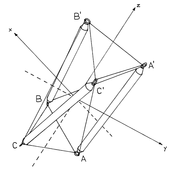
Figure 2.4:  T-Prism:  Cartesian Coordinates
</td></tr></table>

<p>
With Cartesian coordinates, it is no longer convenient to deal with
the parameter <math xmlns="&mathml;"><mi>r</mi></math>,
and instead the common length of each end tendon,
<math xmlns="&mathml;"><mi>u</mi></math>, is used directly.
The constraints imposed by the specification of
fixed lengths for the sides of
the triangles formed by the end tendons must now be explicitly
written out for each triangle:
</p>

<table class="center">
<tr><td><math xmlns="&mathml;"><mrow>
<msup><mover><mi>u</mi><mo>&OverBar;</mo></mover><mn>2</mn></msup>
<mo>=</mo><msup><mi>u</mi><mn>2</mn></msup><mo>=</mo>
<msup><mfenced open="|" close="|"><mover accent="false"><mrow><mi>A</mi>
<mo>&InvisibleTimes;</mo><mi>B</mi></mrow><mo>&OverBar;</mo>
</mover></mfenced><mn>2</mn></msup><mo>=</mo>
<msup><mfenced><mrow><msub><mi>x</mi><mi>A</mi></msub><mo>-</mo>
<msub><mi>x</mi><mi>B</mi></msub></mrow></mfenced><mn>2</mn></msup>
<mo>+</mo>
<msup><mfenced><mrow><msub><mi>y</mi><mi>A</mi></msub><mo>-</mo>
<msub><mi>y</mi><mi>B</mi></msub></mrow></mfenced><mn>2</mn></msup>
<mo>+</mo>
<msup><mfenced><mrow><msub><mi>z</mi><mi>A</mi></msub><mo>-</mo>
<msub><mi>z</mi><mi>B</mi></msub></mrow></mfenced><mn>2</mn></msup>
</mrow></math>
</td></tr>
<tr><td><math xmlns="&mathml;">
<mrow>
  <mphantom>
  <msup><mover><mi>u</mi><mo>&OverBar;</mo></mover><mn>2</mn></msup>
  <mo>=</mo><msup><mi>u</mi><mn>2</mn></msup><mo>=</mo>
  <msup><mfenced open="|" close="|"><mover accent="false"><mrow><mi>A</mi>
  <mo>&InvisibleTimes;</mo><mi>B</mi></mrow><mo>&OverBar;</mo>
  </mover></mfenced><mn>2</mn></msup>
  </mphantom>
<mo>=</mo>
<msup><mfenced><mrow><msub><mi>x</mi><mi>A</mi></msub><mo>-</mo>
<msub><mi>z</mi><mi>A</mi></msub></mrow></mfenced><mn>2</mn></msup>
<mo>+</mo>
<msup><mfenced><mrow><msub><mi>y</mi><mi>A</mi></msub><mo>-</mo>
<msub><mi>x</mi><mi>A</mi></msub></mrow></mfenced><mn>2</mn></msup>
<mo>+</mo>
<msup><mfenced><mrow><msub><mi>z</mi><mi>A</mi></msub><mo>-</mo>
<msub><mi>y</mi><mi>A</mi></msub></mrow></mfenced><mn>2</mn></msup>
</mrow></math>
</td></tr>
<tr><td><math xmlns="&mathml;"><mrow>
<msup><mover><mi>u</mi><mo>&OverBar;</mo></mover><mn>2</mn></msup>
<mo>=</mo><msup><mi>u</mi><mn>2</mn></msup><mo>=</mo>
<msup><mfenced open="|" close="|"><mover accent="false"><mrow><mi>A</mi>
<mo>'</mo><mo>&InvisibleTimes;</mo><mi>B</mi><mo>'</mo></mrow>
<mo>&OverBar;</mo>
</mover></mfenced><mn>2</mn></msup><mo>=</mo>
<msup><mfenced><mrow><msub><mi>x</mi><mrow><mi>A</mi><mo>'</mo></mrow></msub>
<mo>-</mo>
<msub><mi>z</mi><mrow><mi>A</mi><mo>'</mo></mrow></msub></mrow></mfenced>
<mn>2</mn></msup>
<mo>+</mo>
<msup><mfenced><mrow><msub><mi>y</mi><mrow><mi>A</mi><mo>'</mo></mrow></msub>
<mo>-</mo>
<msub><mi>x</mi><mrow><mi>A</mi><mo>'</mo></mrow></msub></mrow></mfenced>
<mn>2</mn></msup>
<mo>+</mo>
<msup><mfenced><mrow><msub><mi>z</mi><mrow><mi>A</mi><mo>'</mo></mrow></msub>
<mo>-</mo>
<msub><mi>y</mi><mrow><mi>A</mi><mo>'</mo></mrow></msub></mrow></mfenced>
<mn>2</mn></msup>
</mrow></math>
</td></tr>
</table>

<p>
Only the constraint for one side
of each triangle is written out since the symmetry of the structure
(which is subsumed in the coordinate representation) ensures that
if the constraint is met for one side of the triangle, the
other sides satisfy the constraint also.  The constraint
imposed by the strut length appears as:
</p>

<p class="center">
<math xmlns="&mathml;"><mrow>
<msup><mover><mi>s</mi><mo>&OverBar;</mo></mover><mn>2</mn></msup>
<mo>=</mo><msup><mi>s</mi><mn>2</mn></msup><mo>=</mo>
<msup><mfenced open="|" close="|"><mover accent="false"><mrow><mi>A</mi>
<mo>&InvisibleTimes;</mo><mi>A</mi><mo>'</mo></mrow><mo>&OverBar;</mo>
</mover></mfenced><mn>2</mn></msup><mo>=</mo>
<msup><mfenced><mrow><msub><mi>x</mi><mi>A</mi></msub>
<mo>-</mo>
<msub><mi>x</mi><mrow><mi>A</mi><mo>'</mo></mrow></msub></mrow></mfenced>
<mn>2</mn></msup>
<mo>+</mo>
<msup><mfenced><mrow><msub><mi>y</mi><mi>A</mi></msub>
<mo>-</mo>
<msub><mi>y</mi><mrow><mi>A</mi><mo>'</mo></mrow></msub></mrow></mfenced>
<mn>2</mn></msup>
<mo>+</mo>
<msup><mfenced><mrow><msub><mi>z</mi><mi>A</mi></msub>
<mo>-</mo>
<msub><mi>z</mi><mrow><mi>A</mi><mo>'</mo></mrow></msub></mrow></mfenced>
<mn>2</mn></msup>
</mrow></math>
</p>

<p>
Again, this equation is not written out for all three
struts since the structure's symmetry ensures that if the
constraint is met for one strut, it is met for the others.
</p>

<p>
Taking all this into consideration, the mathematical
representation of the problem now appears as:
</p>

<p class="center">
<math xmlns="&mathml;"><mtable>
 <mtr><mtd><mtext>minimize</mtext></mtd>
 <mtd>
 <mrow><msup><mi>t</mi><mn>2</mn></msup><mo>=</mo>
 <msup><mfenced open="|" close="|"><mover accent="false"><mrow><mi>A</mi>
 <mo>&InvisibleTimes;</mo><mi>C</mi><mo>'</mo></mrow><mo>&OverBar;</mo>
 </mover></mfenced><mn>2</mn></msup><mo>=</mo>
 <msup><mfenced><mrow><msub><mi>x</mi><mi>A</mi></msub>
 <mo>-</mo>
 <msub><mi>y</mi><mrow><mi>A</mi><mo>'</mo></mrow></msub></mrow></mfenced>
 <mn>2</mn></msup>
 <mo>+</mo>
 <msup><mfenced><mrow><msub><mi>y</mi><mi>A</mi></msub>
 <mo>-</mo>
 <msub><mi>z</mi><mrow><mi>A</mi><mo>'</mo></mrow></msub></mrow></mfenced>
 <mn>2</mn></msup>
 <mo>+</mo>
 <msup><mfenced><mrow><msub><mi>z</mi><mi>A</mi></msub>
 <mo>-</mo>
 <msub><mi>x</mi><mrow><mi>A</mi><mo>'</mo></mrow></msub></mrow></mfenced>
 <mn>2</mn></msup>
 </mrow>
 </mtd></mtr>

 <mtr><mtd><mrow>
 <msub><mi>x</mi><mi>A</mi></msub><mo>,</mo>
 <msub><mi>y</mi><mi>A</mi></msub><mo>,</mo>
 <msub><mi>z</mi><mi>A</mi></msub></mrow></mtd>
 </mtr>
 <mtr><mtd><mrow>
 <msub><mi>x</mi><mrow><mi>A</mi><mo>'</mo></mrow></msub><mo>,</mo>
 <msub><mi>y</mi><mrow><mi>A</mi><mo>'</mo></mrow></msub><mo>,</mo>
 <msub><mi>z</mi><mrow><mi>A</mi><mo>'</mo></mrow></msub></mrow></mtd>
 </mtr>
 <mtr><mtd><mtext>&nbsp;</mtext></mtd></mtr>
 <mtr><mtd><mtext>subject to</mtext></mtd>
 <mtd><mrow>
 <msup><mover><mi>u</mi><mo>&OverBar;</mo></mover><mn>2</mn></msup>
 <mo>=</mo><msup><mi>u</mi><mn>2</mn></msup><mo>=</mo>
 <msup><mfenced open="|" close="|"><mover accent="false"><mrow><mi>A</mi>
 <mo>&InvisibleTimes;</mo><mi>B</mi></mrow><mo>&OverBar;</mo>
 </mover></mfenced><mn>2</mn></msup><mo>=</mo>
<msup><mfenced><mrow><msub><mi>x</mi><mi>A</mi></msub><mo>-</mo>
<msub><mi>z</mi><mi>A</mi></msub></mrow></mfenced><mn>2</mn></msup>
<mo>+</mo>
<msup><mfenced><mrow><msub><mi>y</mi><mi>A</mi></msub><mo>-</mo>
<msub><mi>x</mi><mi>A</mi></msub></mrow></mfenced><mn>2</mn></msup>
<mo>+</mo>
<msup><mfenced><mrow><msub><mi>z</mi><mi>A</mi></msub><mo>-</mo>
<msub><mi>y</mi><mi>A</mi></msub></mrow></mfenced><mn>2</mn></msup>
 </mrow></mtd></mtr>
 <mtr><mtd><mtext>&nbsp;</mtext></mtd>
 <mtd><mrow>
 <msup><mover><mi>u</mi><mo>&OverBar;</mo></mover><mn>2</mn></msup>
 <mo>=</mo><msup><mi>u</mi><mn>2</mn></msup><mo>=</mo>
 <msup><mfenced open="|" close="|"><mover accent="false"><mrow><mi>A</mi>
 <mo>'</mo><mo>&InvisibleTimes;</mo><mi>B</mi><mo>'</mo></mrow>
 <mo>&OverBar;</mo>
 </mover></mfenced><mn>2</mn></msup><mo>=</mo>
<msup><mfenced><mrow><msub><mi>x</mi><mrow><mi>A</mi><mo>'</mo></mrow></msub>
<mo>-</mo>
<msub><mi>z</mi><mrow><mi>A</mi><mo>'</mo></mrow></msub></mrow></mfenced>
<mn>2</mn></msup>
<mo>+</mo>
<msup><mfenced><mrow><msub><mi>y</mi><mrow><mi>A</mi><mo>'</mo></mrow></msub>
<mo>-</mo>
<msub><mi>x</mi><mrow><mi>A</mi><mo>'</mo></mrow></msub></mrow></mfenced>
<mn>2</mn></msup>
<mo>+</mo>
<msup><mfenced><mrow><msub><mi>z</mi><mrow><mi>A</mi><mo>'</mo></mrow></msub>
<mo>-</mo>
<msub><mi>y</mi><mrow><mi>A</mi><mo>'</mo></mrow></msub></mrow></mfenced>
<mn>2</mn></msup>
 </mrow></mtd></mtr>
 <mtr><mtd><mtext>&nbsp;</mtext></mtd>
 <mtd><mrow>
 <msup><mover><mi>s</mi><mo>&OverBar;</mo></mover><mn>2</mn></msup>
 <mo>=</mo><msup><mi>s</mi><mn>2</mn></msup><mo>=</mo>
 <msup><mfenced open="|" close="|"><mover accent="false"><mrow><mi>A</mi>
 <mo>&InvisibleTimes;</mo><mi>A</mi><mo>'</mo></mrow><mo>&OverBar;</mo>
 </mover></mfenced><mn>2</mn></msup><mo>=</mo>
 <msup><mfenced><mrow><msub><mi>x</mi><mi>A</mi></msub>
 <mo>-</mo>
 <msub><mi>x</mi><mrow><mi>A</mi><mo>'</mo></mrow></msub></mrow></mfenced>
 <mn>2</mn></msup>
 <mo>+</mo>
 <msup><mfenced><mrow><msub><mi>y</mi><mi>A</mi></msub>
 <mo>-</mo>
 <msub><mi>y</mi><mrow><mi>A</mi><mo>'</mo></mrow></msub></mrow></mfenced>
 <mn>2</mn></msup>
 <mo>+</mo>
 <msup><mfenced><mrow><msub><mi>z</mi><mi>A</mi></msub>
 <mo>-</mo>
 <msub><mi>z</mi><mrow><mi>A</mi><mo>'</mo></mrow></msub></mrow></mfenced>
 <mn>2</mn></msup>
 </mrow></mtd></mtr>
 <mtr><mtd><mtext>&nbsp;</mtext></mtd><mtd><mrow>
 <mover><mi>d</mi><mo>&OverBar;</mo></mover><mo>=</mo>
 <msub><mi>x</mi><mi>A</mi></msub><mo>+</mo>
 <msub><mi>y</mi><mi>A</mi></msub><mo>+</mo>
 <msub><mi>z</mi><mi>A</mi></msub>
 </mrow></mtd></mtr>
 <mtr><mtd><mtext>&nbsp;</mtext></mtd><mtd><mrow>
 <mn>0</mn><mo>=</mo>
 <msub><mi>x</mi><mi>A</mi></msub><mo>-</mo>
 <msub><mi>z</mi><mi>A</mi></msub>
 </mrow></mtd></mtr>
</mtable>
</math>
</p>

<p>
The final two constraints are added for computational reasons. 
Without these constraints, the problem has infinitely many
solutions.<sup><a href="#tx12" id="rf12">12</a></sup>
</p>

<p>
These equations don't lend themselves to the easy substitutions
that the previous set up did, and, in this problem, certainly the
previous approach is to be preferred since it is so simple to
solve.  The problem with the earlier approach is that it doesn't
generalize as easily to more complex problems as this Cartesian
approach does.
</p>

<p>
Given the complexities involved in solving a system like this,
the discussion of how the solution is obtained is
deferred until later when the problems absolutely require it.
</p>

<p class="section-header-level2" id="tprism_general">
2.2.4&nbsp;T-Prism Mathematics:  Further Generalizations
</p>

<p>
<a href="refs.html#Kenner76"><i>Kenner76</i></a>
shows how the formulae of <a href="#tprism_math_cyl">Section&nbsp;2.2.2</a>
can be generalized to handle
four-fold and higher-symmetry prisms and cases where the
radii of the ends differ.  For the higher-symmetry prisms,
it is also not necessary that the side tendon be restricted to connecting
adjacent struts:  it can skip over one or more struts in its trip from one
end of the prism to the other.  Although
<a href="refs.html#Kenner76"><i>Kenner76</i></a> doesn't explore
this possibility, it is easy enough to generalize his formulae to
handle it.
</p>

<div id="footnotes">
<hr class="footmark"/>
<p class="note">
<sup><a href="#rf1" id="tx1">1</a></sup>
  <a href="refs.html#Gough98"><i>Gough98</i></a>, Fig.&nbsp;13,
  p.&nbsp;106, shows a tensegrity prism which claims to be
  a modern reconstruction of Ioganson's sculpture which was
  destroyed in the mid-1920's by the Soviet regime.
  Kenneth Snelson does not believe such a reconstruction is credible
  based only on the old exhibition photo which is of poor quality
  (see <i>Gough98</i>, Fig.&nbsp;2 and Fig.&nbsp;9, where the structure
  is labeled "IX" at its base).
  In his view, only someone who already knew about tensegrity
  prisms could make such a reconstruction; the necessary connections
  are not evident from the photo itself.
  </p>

  <p class="note-continued">
  Snelson's observations seem correct, but the apparent equal lengths of
  the two readily visible struts, the consistency of the apparent
  trajectory of the less visible one with a 30&deg; twist, and the
  improbability of being able to configure the struts the way they are
  with another arrangement of tendons would seem to point to Ioganson's
  priority here.  That being said, the prism does not catch the imagination
  the way Snelson's X-Piece does.  No floating of struts is readily observable.
  So even if priority is granted to Ioganson here, it would still seem
  the step to a structure like Snelson's is a significant one, even if
  considered as only an outgrowth of the prism which of course it was not.
  </p>

  <p class="note-continued">
  As was noted in <a href="chap1.html#early">Section&nbsp;1.3</a>,
  the tensegrity prism was the first tensegrity structure assembled by
  Emmerich in 1958.  It appears as Fig.&nbsp;1 in his French Patent
  No.&nbsp;1,377,290.
  It also appears as Fig.&nbsp;22b in Snelson's U.S. Patent No.&nbsp;3,169,611,
  but only as prior art.  In the U.S., the tensegrity prism was
  apparently developed shortly after Snelson's X-Piece
  revelation since John Moelman's Tensegrity Vector Equilibrium
  (see <a href="refs.html#Fuller73"><i>Fuller73</i></a>, Fig. 271), developed
  in 1951, is clearly two prisms bonded end-to-end.
  </p>

<p class="note">
<sup><a href="#rf2" id="tx2">2</a></sup>
  Small screw eyes, 7-8&nbsp;mm in diameter, work the best.
  Likely candidates can be found in
  hardware stores or picture framing shops.
  Anthony Pugh (<a href="refs.html#Pugh76"><i>Pugh76</i></a>, p.&nbsp;72)
  favors nails instead of screw eyes.  Nails have the advantage that
  <i>ad hoc</i> adjustments of the member lengths don't have to be made to
  accommodate the dimensions of the attachment point.  Pugh's detailed
  information on tensegrity model construction is recommended reading.
  </p>

<p class="note">
<sup><a href="#rf3" id="tx3">3</a></sup>
  A stunsail tack bend (used in sailing) is an
  effective knot in this application.  If problems are encountered tying
  the fishing line to the right length, thin-gauge wire can be used.
  This doesn't have to be knotted but merely twisted at the
  right length.  The sharp wire ends can be a hazard.
  </p>

<p class="note">
<sup><a href="#rf4" id="tx4">4</a></sup>
  The minimum is obtained when the two ends are twisted
  150&deg; relative to each other.
  </p>

<p class="note">
<sup><a href="#rf5" id="tx5">5</a></sup>
  A presentation of this system can be found in most calculus
  texts, for instance <a href="refs.html#Leithold72"><i>Leithold72</i></a>,
  p.&nbsp;863.
  </p>

<p class="note">
<sup><a href="#rf6" id="tx6">6</a></sup>
  The value can be expressed in radians or
  degrees.  Here, for mathematical convenience, radians are primarily used.
  </p>

<p class="note">
<sup><a href="#rf7" id="tx7">7</a></sup>
  This is implicitly the solution sought in the
  experiment with the t-prism carried out above.  The struts were
  fixed in length and the t-prism was twisted until the opposite
  rectangle ends were as close together as possible.
  </p>

<p class="note">
<sup><a href="#rf8" id="tx8">8</a></sup>
  For example, instead of constraining the strut length to
  be a certain value, the second power of the strut length can be
  constrained to the the second power of that certain value, and
  the effect of the constraint is the same.
  </p>

<p class="note">
<sup><a href="#rf9" id="tx9">9</a></sup>
  Here an important mathematical advantage of expressing the
  angular measures in terms of radians is realized:  the derivative
  of <math xmlns="&mathml;"><mrow><mo>cos</mo></mrow></math> is simply
  <math xmlns="&mathml;">
  <mrow><mo>-</mo><mrow><mo>sin</mo></mrow></mrow></math>.
  The result is equated to 0
  since that is a necessary first-order condition for a minimum.
  </p>

<p class="note">
<sup><a href="#rf10" id="tx10">10</a></sup>
  The difference between the two angles in question is
<math xmlns="&mathml;"><mrow>
  <mi>&theta;</mi><mo>-</mo>
  <mfrac>
    <mrow>
      <mi>2</mi><mo>&InvisibleTimes;</mo><mi>&pi;</mi>
    </mrow>
    <mi>3</mi>
  </mfrac>
</mrow></math> and that for
<math xmlns="&mathml;"><mi>C</mi><mo>'</mo></math> is
<math xmlns="&mathml;"><mrow>
  <mi>&theta;</mi><mo>-</mo>
  <mfenced>
  <mrow>
  <mi>&theta;</mi><mo>-</mo>
  <mfrac>
    <mrow>
      <mi>2</mi><mo>&InvisibleTimes;</mo><mi>&pi;</mi>
    </mrow>
    <mi>3</mi>
  </mfrac>
  </mrow>
  </mfenced>
  <mo>=</mo>
  <mfrac>
    <mrow>
      <mi>2</mi><mo>&InvisibleTimes;</mo><mi>&pi;</mi>
    </mrow>
    <mi>3</mi>
  </mfrac>
</mrow>
</math>
  which is not an even multiple of <math xmlns="&mathml;"><mi>&pi;</mi></math>.
  </p>

<p class="note">
<sup><a href="#rf11" id="tx11">11</a></sup>
  These would involve substituting other odd multiples of
  <math xmlns="&mathml;"><mi>&pi;</mi></math>
  besides <math xmlns="&mathml;"><mi>&pi;</mi></math> and
  <math xmlns="&mathml;"><mo>-</mo><mi>&pi;</mi></math>
  into the equations above.
  </p>

<p class="note">
<sup><a href="#rf12" id="tx12">12</a></sup>
  The fourth constraint requires the base of the t-prism to
  fall in a fixed plane orthogonal to the vector
  <math xmlns="&mathml;"><mfenced><mn>1</mn><mn>1</mn><mn>1</mn>
  </mfenced></math>.
  The fifth constraint fixes the t-prism with respect to rotations
  about its central axis.
  </p>
</div>

<p class="link">
<a href="index.html#chap2_2">Table of Contents</a><br/>
2.3&nbsp;<a href="chap2_3.xml">T-Icosahedron:  A Diamond Tensegrity</a>
</p>

</body>
</html>
