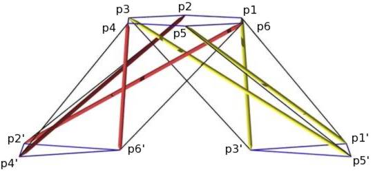
Wishbone Tensegrity with Point Labels
structure file: tprism/x6prism8c.rc
variable file: tprism/x6prism8c.dat
digit list: src/standard.dls
|
        Member Descriptions
        [name, end point names, weight (if in objective function),
        second power of length (if a constraint), member category,
        Obj/Con/Exc (put in objective function, use as a constraint or
        exclude from computations), flags]
        For assembly purposes, only the name and end point names are
        of interest.  The other information may be of interest after
        A Practical Guide to Tensegrity Design has been consulted.

# strut
<Member> struta1    p3' p1  -1.0  sqr(3.0) 1 Obj *
<Member> struta2    p5' p3  -1.0  sqr(3.0) 1 Obj *
<Member> struta3    p1' p5  -1.0  sqr(3.0) 1 Obj *
<Member> strutb1    p4' p2  -1.0  sqr(3.0) 9 Obj *
<Member> strutb2    p6' p4  -1.0  sqr(3.0) 9 Obj *
<Member> strutb3    p2' p6  -1.0  sqr(3.0) 9 Obj *

# interlayer tendon
<Member> xlta1      p1' p1   1.0  sqr(2.60841859702260) 3 Con *
<Member> xltb1      p2' p2   1.0  sqr(3.20436408549826) 3 Con *
<Member> xlta2      p3' p3   1.0  sqr(2.78065654253971) 3 Con *
<Member> xltb2      p4' p4   1.0  sqr(2.60841859702260) 3 Con *
<Member> xlta3      p5' p5   1.0  sqr(3.20436408549826) 3 Con *
<Member> xltb3      p6' p6   1.0  sqr(2.78065654253971) 3 Con *

# end tendons
<Member> end1      p2  p1   1.0  1.0      2 Con *
<Member> end2      p3  p2   1.0  1.0      2 Con *
<Member> end3      p4  p3   1.0  1.0      2 Con *
<Member> end4      p5  p4   1.0  1.0      2 Con *
<Member> end5      p6  p5   1.0  1.0      2 Con *
<Member> end6      p1  p6   1.0  1.0      2 Con *
<Member> enda1'    p3' p1'  1.0  3.0      4 Con *
<Member> endb1'    p4' p2'  1.0  3.0      4 Con *
<Member> enda2'    p5' p3'  1.0  3.0      4 Con *
<Member> endb2'    p6' p4'  1.0  3.0      4 Con *
<Member> enda3'    p1' p5'  1.0  3.0      4 Con *
<Member> endb3'    p2' p6'  1.0  3.0      4 Con *
        In-Situ Member Lengths
        These are the lengths of the members when they are in place
        and prestress is applied.  The strut lengths are from pin insertion
        point to pin insertion point, as are the tendon lengths.
        The values are in model units.

  struta1:       2.0659   struta2:      4.14682   struta3:      3.70568
  strutb1:      3.70568   strutb2:       2.0659   strutb3:      4.14682
    xlta1:      2.60842     xltb1:      3.20436     xlta2:      2.78066
    xltb2:      2.60842     xlta3:      3.20436     xltb3:      2.78066
     end1:            1      end2:            1      end3:            1
     end4:            1      end5:            1      end6:            1
   enda1':      1.73205    endb1':      1.73205    enda2':      1.73205
   endb2':      1.73205    enda3':      1.73205    endb3':      1.73205
        Relative Member Force Magnitudes
        These values are useful for developing an assembly
        strategy for the structure.  The tighter tendons are much
        easier to tie in place early on, while the looser tendons
        can be left to the last.  This information is also used
        to adjust tendon lengths since the measured length of a tendon
        will be shorter for a highly-stressed tendon with the same
        in-situ length as a tendon which is not so stressed.
        If you think the relative member forces are somewhat correlated
        with the member lengths, you are right.

  struta1:     -2.06590   struta2:     -4.14682   struta3:     -3.70568
  strutb1:     -3.70568   strutb2:      -2.0659   strutb3:     -4.14682
    xlta1:      2.60842     xltb1:      3.20436     xlta2:      2.78066
    xltb2:      2.60842     xlta3:      3.20436     xltb3:      2.78066
     end1:      1.73205      end2:      1.73205      end3:      1.73205
     end4:      1.73205      end5:      1.73205      end6:      1.73205
   enda1':            1    endb1':            1    enda2':            1
   endb2':            1    enda3':            1    endb3':            1
        Construction Lengths (in inches, sixteenths and thirty-seconds)
        The construction length of a tendon is less than the in-situ
        length since when the tendon is measured off it isn't under
        any prestress force.  The construction length for the strut
        represents the length of the 3/16-inch-diameter wooden dowel.
        The tendons were made of 12-lb.-test braided nylon fishing line.
        In this case, the attachment point at the hubs was a simple
        metal pin stuck into the end of the strut, so no member-length
        adjustments were necessary.  Prestress forces are assumed
        not to affect strut lengths.

        Elongation of Tendon of Unit Cross Section
        Under Force of Average Magnitude (fraction)> .02
        Length Scale Factor> 9/5 (scaled for a total length of 9 inches)
        Strut and Tendon Hub Adjustments - s;t> 0 0

  struta1:   3 11 1   struta2:   7  7 1   struta3:   6 10 1   strutb1:   6 10 1
  strutb2:   3 11 1   strutb3:   7  7 1     xlta1:   4  9 0     xltb1:   5  9 0
    xlta2:   4 14 0     xltb2:   4  9 0     xlta3:   5  9 0     xltb3:   4 14 0
     end1:   1 12 1      end2:   1 12 1      end3:   1 12 1      end4:   1 12 1
     end5:   1 12 1      end6:   1 12 1    enda1':   3  1 1    endb1':   3  1 1
   enda2':   3  1 1    endb2':   3  1 1    enda3':   3  1 1    endb3':   3  1 1
Wishbone Tensegrity with Point Labels
structure file:  tprism/x6prism8c.rc
 variable file:  tprism/x6prism8c.dat
    digit list:  src/standard.dls
|
|
CONTACT: Bob Burkhardt Tensegrity Solutions Box 426164 Cambridge, MA 02142-0021 USA e-mail: bobwb@juno.com |