 |
 |
 |
(VRML Model)
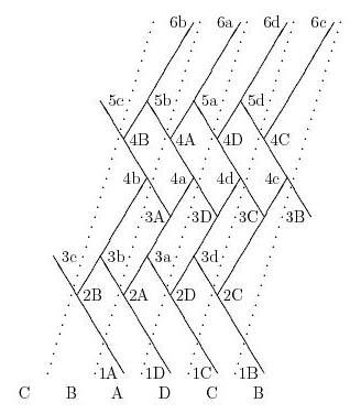
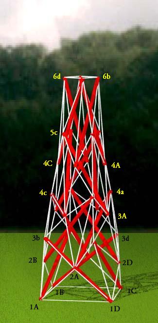
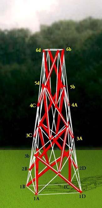
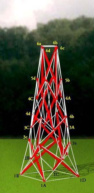
Schematic for the Triangulated Tensegrity Obelisk
        Member Descriptions
        [name, end point names, weight (if in objective function),
        second power of length (if a constraint), member category,
        Obj/Con/Exc (put in objective function, use as a constraint or
        exclude from computations), flags]
        For assembly purposes, only the name and end point names are
        of interest.  The other information may be of interest after
        A Practical Guide to Tensegrity Design has been consulted.

<Member> strut13 pt1A pt3c 0.0 sqr(2.5) 1 Con CalcClear Inelastic *
<Member> strut24 pt2A pt4a 0.0 sqr(2.5) 1 Con CalcClear Inelastic *
<Member> strut35 pt3A pt5c 0.0 sqr(2.5) 1 Con CalcClear Inelastic *
<Member> strut46 pt4A pt6a 0.0 sqr(2.5) 1 Con CalcClear Inelastic *

<Member> baset  pt1A pt1B 0.0  sqr(1.9) 2 Con *
<Member> apext  pt6a pt6b 0.0  sqr(1.9/3) 2 Con *

<Member> guy1   pt1A pt3b 0.10  0.0      3 Obj *
<Member> guy2   pt2A pt4b 0.20  0.0      3 Obj *
<Member> guy3   pt3A pt5b 0.20  0.0      3 Obj *
<Member> guy4   pt4A pt6b 0.10  0.0      3 Obj *

<Member> TL12   pt1A pt2B 0.9  0.0      4 Obj *
<Member> TS23   pt2A pt3b 1.0  0.0      4 Obj *
<Member> TL23   pt2A pt3A 0.9  0.0      4 Exc *
<Member> tS23   pt2A pt3a 1.0  0.0      4 Obj *
<Member> TS34   pt3A pt4a 1.1  0.0      4 Obj *
<Member> TL34   pt3A pt4B 0.9  0.0      4 Exc *
<Member> tS34   pt3A pt4b 1.1  0.0      4 Obj *
<Member> tL34   pt3a pt4a 0.9  0.0      4 Exc *
<Member> TS45   pt4A pt5b 1.2  0.0      4 Obj *
<Member> tS45   pt4A pt5a 1.2  0.0      4 Obj *
<Member> tL45   pt4d pt5a 0.9  0.0      4 Exc *
<Member> tL56   pt5a pt6a 0.9  0.0      4 Obj *
<Member> tT33   pt3a pt3A 2/3  0.0      4 Obj *
<Member> tT44   pt4a pt4A 2/3  0.0      4 Obj *

<Member> xtr1   pt1A pt2A 0.1  0.0      7 Obj *
<Member> xtr2   pt2A pt3B 0.1  0.0      7 Obj *
<Member> xtr3   pt3A pt4A 0.1  0.0      7 Obj *

<Member> xtr4   pt3a pt4b 0.14 0.0      7 Obj *
<Member> xtr5   pt4a pt5a 0.10 0.0      7 Obj *
<Member> xtr6   pt5a pt6b 0.12 0.0      7 Obj *


        In-Situ Member Lengths
        These are the lengths of the members when they are in place
        and prestress is applied.  These are raw unadjusted values and
        assume the hubs of the structure are single points.  The
        values are in model units.

  strut13:          2.5   strut24:          2.5   strut35:          2.5
  strut46:          2.5     baset:          1.9     apext:     0.633333
     guy1:      1.66175      guy2:      1.96864      guy3:      2.23353
     guy4:       2.3468      TL12:      1.30665      TS23:      1.27839
     TL23:      1.70955      tS23:     0.878816      TS34:     0.919302
     TL34:       1.5853      tS34:     0.776239      tL34:      1.79612
     TS45:      1.00054      tS45:     0.997978      tL45:      1.88638
     tL56:      1.55026      tT33:      0.91207      tT44:     0.901221
     xtr1:      1.26893      xtr2:      1.40126      xtr3:      1.34063
     xtr4:      1.19009      xtr5:      1.66707      xtr6:      1.47086


        Relative Member Prestress Force Magnitudes
        These values are useful for developing an assembly
        strategy for the structure.  The tighter tendons are much
        easier to tie in place early on, while the looser tendons
        can be left to the last.  This information is also used
        to adjust tendon lengths since the measured length of a tendon
        will be shorter for a highly-stressed tendon with the same
        in-situ length as a tendon which is not so stressed.

  strut13:     -1.61292   strut24:     -1.43981   strut35:     -1.41234
  strut46:     -1.83596     baset:     0.286017     apext:     0.229667
     guy1:     0.166175      guy2:     0.393727      guy3:     0.446705
     guy4:      0.23468      TL12:      1.17599      TS23:      1.27839
     tS23:     0.878816      TS34:      1.01123      tS34:     0.853863
     TS45:      1.20065      tS45:      1.19757      tL56:      1.39523
     tT33:     0.608047      tT44:     0.600814      xtr1:     0.126893
     xtr2:     0.140126      xtr3:     0.134063      xtr4:     0.166612
     xtr5:     0.166707      xtr6:     0.176504

        Average tendon force magnitude: 0.584931


        Construction Lengths (in inches, 16ths and 32nds)
        The construction length of a tendon is less than the in-situ
        length since when the tendon is measured off it isn't under
        any prestress force.  The construction length for a member
        represents the distance between the locations where it
        departs from the hub.  The struts were cut from
        1-inch by 1-inch hardwood garden stakes.  The tendon material
        was single strands of twisted #18 nylon twine.  Its behavior
        under stress is highly non-linear, so a look-up table
        was used to compute strains.  Prestress forces were assumed
        to affect tendon lengths and not strut lengths.

        Average Tendon Force Magnitude (chart units)> 20
        Length Scale Factor> 48/2.5
        Strut and Tendon Hub Adjustments> 0 0.5
        (adjust the tendon lengths by subtracting a half inch from
         both ends)

  strut13:  48  0 0  strut24:  48  0 0  strut35:  48  0 0  strut46:  48  0 0
    baset:  34  6 0    apext:  10 14 0     guy1:  30  5 0     guy2:  35  5 1
     guy3:  40  1 0     guy4:  42 13 1     TL12:  22  0 1     TS23:  21  7 0
     tS23:  14 12 0     TS34:  15  6 0     tS34:  12 15 0     TS45:  16 10 0
     tS45:  16  9 1     tL56:  26  1 0     tT33:  15  9 1     tT44:  15  6 1
     xtr1:  23  0 0     xtr2:  25  7 1     xtr3:  24  5 1     xtr4:  21  7 0
     xtr5:  30  6 1     xtr6:  26 11 0


        Material Quantities
        This provides an estimate of how much material will
        be needed to assemble the structure, in this case
        inches of garden stake and inches of nylon twine.
        The lengths must be adjusted to take into account the
        fact that the strut extends past the hub and some length
        of tendon is required to tie it to the strut.
        The Quantity value given for each Type does not take
        into account the Cross Section value.  The total
        Quantity given across from Tndns does.
        The Cross Section value of 2 indicates all the twine
        strands were doubled up, i.e. two lengths of twine were
        used to tie each tendon.

        Length Scale Factor> 48/2.5
        Strut and Tendon Adjustments> (-1) (-6)

                   Cross
         Type     Section    Quantity Count

            1           1         800    16
            2           2     281.872     8
            3           2     795.605    16
            4           2     1187.24    40
            7           2     911.798    24
        Strts                     800    16
        Tndns                 6353.02    88
|
|
|
Schematic for the Triangulated Tensegrity Obelisk
          structure file:  obelisk3/x4l4obelisk1.rc
           variable file:  obelisk3/x4l4obelisk1.dat
stress-strain chart file:  v04oct_d/wellingtn.ssc
         digit list file:  src/standard.dls
     cross-section table:  src/double.cst
|
CONTACT:
Bob Burkhardt
Tensegrity Solutions
Box 426164
Cambridge, MA 02142-0021
USA
e-mail: bobwb@juno.com