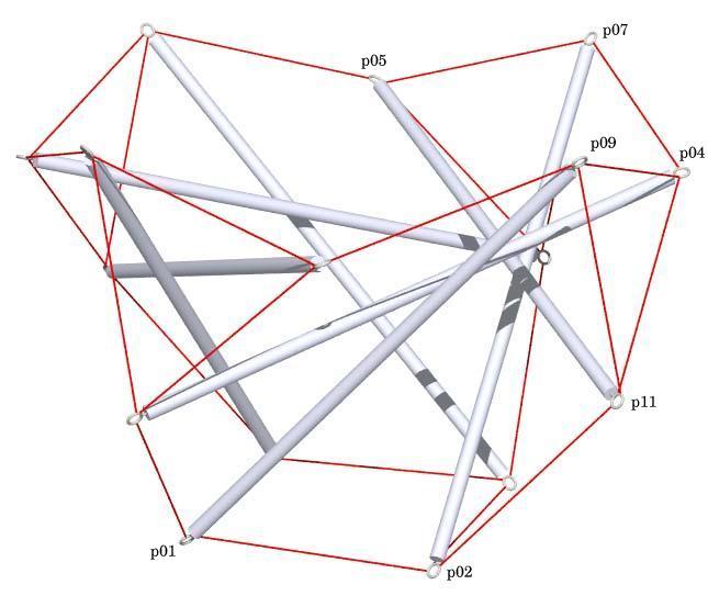
View of the Tensegrity Tulip
with Point Labels
        Hub Connectivity
        This shows how hub vectors (hv01.1 ...) are applied to the
        strut end points (p01 ...) to derive hub points (hp01.1 ...).
        Hub points are where tendons are connected to the strut.

<VecPt>   hp01.1   p01  +  hv01.1
<VecPt>   hp01.2   p01  +  hv01.2
<VecPt>   hp01.3   p01  +  hv01.3
<VecPt>   hp05.1   p05  +  hv05.1
<VecPt>   hp05.2   p05  +  hv05.2
<VecPt>   hp05.3   p05  +  hv05.3
<VecPt>   hp09.1   p09  +  hv09.1
<VecPt>   hp09.2   p09  +  hv09.2
<VecPt>   hp09.3   p09  +  hv09.3
<VecPt>   hp11.1   p11  +  hv11.1
<VecPt>   hp11.2   p11  +  hv11.2
<VecPt>   hp11.3   p11  +  hv11.3


        Transformations
        This shows how transforms are defined and how they are
        applied to derive transformed objects from basic objects.

# rotation matrices
<XMat> x4 cos(2*pi/4) (-sin(2*pi/4)) 0 sin(2*pi/4) cos(2*pi/4) 0 0 0 1
<CompositeXform> x4^2 x4 x4
<CompositeXform> x4^3 x4 x4^2

# transform points and vectors
<XformPt>  p02     p01     x4
<XformPt>  hp02.1  hp01.1  x4
<XformPt>  hp02.2  hp01.2  x4
<XformPt>  hp02.3  hp01.3  x4
<XformPt>  p04     p05     x4^3
<XformPt>  hp04.1  hp05.1  x4^3
<XformPt>  hp04.2  hp05.2  x4^3
<XformPt>  hp04.3  hp05.3  x4^3
<XformPt>  p07     p09     x4
<XformPt>  hp07.1  hp09.1  x4
<XformPt>  hp07.2  hp09.2  x4
<XformPt>  hp07.3  hp09.3  x4


        Member Descriptions
        [name, end point names, weight (if in objective function),
        second power of length (if a constraint), member category,
        Obj/Con/Exc (put in objective function, use as a constraint or
        exclude from computations), flags]
        For assembly purposes, only the name and end point names are
        of interest.  The other information may be of interest after
        A Practical Guide to Tensegrity Design has been consulted.

# struts
<Member> strut1   p01   p09    0.00   sqr(317)   1 Con CalcClear *
<Member> strut2   p05   p11    0.00   sqr(317)   1 Con CalcClear *

# square tendon
<Member> sqten    hp01.1  hp02.2    0.00   sqr(129.2792)   2 Con *

# triangle tendons
<Member> triten1  hp04.1  hp09.1    0.00   sqr(129.2792)   2 Con *
<Member> triten2  hp09.2  hp11.1    0.00   sqr(129.2792)   2 Con *
<Member> triten3  hp11.2  hp04.2    0.00   sqr(129.2792)   2 Con *

# zig-zag tendons
<Member> zzten1   hp02.3  hp11.3    1.00   0.00            3 Obj *
<Member> zzten2   hp04.3  hp07.3    1.00   sqr(129.2792)   3 Con *


        Hub Constructs
        These items are just vectors corresponding to each of the
        struts.  At some point the software will be modified so
        these items aren't necessary since it should be possible
        to treat any member as a vector without explicit constructs.

<DiffVec>    strut1v     p01     p09
<DiffVec>    strut2v     p05     p11


        Hub Constraints
        These are constraints the hub vectors must meet.  For
        these constraints to be specified, a set of
        center vectors (cv01, ...) is introduced.  There is one
        center vector for each strut end point.  The center vectors
        are constrained to be orthogonal to the strut.  For each
        tendon connected to a strut end point, there is a hub
        vector.  All the hub vectors at a strut end point must
        be orthogonal to the corresponding center vector and
        4 mm long.  4 mm is the outer radius of the screw eye.
        The center vectors are constrained to be of length one
        just to make their values well defined.

<VecDotVec>  hubdot01    strut1v cv01 1.0  0.0         Con
<VecLength>  cvlen01     cv01         1.0  sqr(1.0)    Con
<VecDotVec>  hubdot01.1  cv01 hv01.1  1.0  0.0         Con
<VecDotVec>  hubdot01.2  cv01 hv01.2  1.0  0.0         Con
<VecDotVec>  hubdot01.3  cv01 hv01.3  1.0  0.0         Con
<VecLength>  hvlen01.1   hv01.1       1.0  sqr(4.0)    Con
<VecLength>  hvlen01.2   hv01.2       1.0  sqr(4.0)    Con
<VecLength>  hvlen01.3   hv01.3       1.0  sqr(4.0)    Con
<VecDotVec>  hubdot09    strut1v cv09 1.0  0.0         Con
<VecLength>  cvlen09     cv09         1.0  sqr(1.0)    Con
<VecDotVec>  hubdot09.1  cv09 hv09.1  1.0  0.0         Con
<VecDotVec>  hubdot09.2  cv09 hv09.2  1.0  0.0         Con
<VecDotVec>  hubdot09.3  cv09 hv09.3  1.0  0.0         Con
<VecLength>  hvlen09.1   hv09.1       1.0  sqr(4.0)    Con
<VecLength>  hvlen09.2   hv09.2       1.0  sqr(4.0)    Con
<VecLength>  hvlen09.3   hv09.3       1.0  sqr(4.0)    Con
<VecDotVec>  hubdot05    strut2v cv05 1.0  0.0         Con
<VecLength>  cvlen05     cv05         1.0  sqr(1.0)    Con
<VecDotVec>  hubdot05.1  cv05 hv05.1  1.0  0.0         Con
<VecDotVec>  hubdot05.2  cv05 hv05.2  1.0  0.0         Con
<VecDotVec>  hubdot05.3  cv05 hv05.3  1.0  0.0         Con
<VecLength>  hvlen05.1   hv05.1       1.0  sqr(4.0)    Con
<VecLength>  hvlen05.2   hv05.2       1.0  sqr(4.0)    Con
<VecLength>  hvlen05.3   hv05.3       1.0  sqr(4.0)    Con
<VecDotVec>  hubdot11    strut2v cv11 1.0  0.0         Con
<VecLength>  cvlen11     cv11         1.0  sqr(1.0)    Con
<VecDotVec>  hubdot11.1  cv11 hv11.1  1.0  0.0         Con
<VecDotVec>  hubdot11.2  cv11 hv11.2  1.0  0.0         Con
<VecDotVec>  hubdot11.3  cv11 hv11.3  1.0  0.0         Con
<VecLength>  hvlen11.1   hv11.1       1.0  sqr(4.0)    Con
<VecLength>  hvlen11.2   hv11.2       1.0  sqr(4.0)    Con
<VecLength>  hvlen11.3   hv11.3       1.0  sqr(4.0)    Con


        In-Situ Member Lengths
        These are the lengths of the members when they are in place
        and prestress is applied.  The strut lengths are from
        screw-eye center to screw-eye center.  The tendon lengths
        are from screw-eye rim to screw-eye rim.  Since the model
        has been scaled appropriately, these values are in millimeters.

   strut1:          317    strut2:          317     sqten:      129.279
  triten1:      129.279   triten2:      129.279   triten3:      129.279
   zzten1:      129.279    zzten2:      129.279


        Relative Member Prestress Force Magnitudes
        These values are useful for developing an assembly
        strategy for the structure.  The tighter tendons are much
        easier to tie in place early on, while the looser tendons
        can be left to the last.  This information is also used
        to adjust tendon lengths since the measured length of a tendon
        will be shorter for a highly-stressed tendon with the same
        in-situ length as a tendon which is not so stressed.

   strut1:     -129.702    strut2:     -133.842     sqten:      79.7366
  triten1:      83.7261   triten2:      32.1339   triten3:      150.757
   zzten1:      129.279    zzten2:      135.186


        Construction Lengths (in millimeters and halves)
        The construction length of a tendon is less than the in-situ
        length since when the tendon is measured off it isn't under
        any prestress force.  The construction length for the strut
        represents the length of the wooden dowel.  Prestress forces
        are assumed to affect tendon lengths and not strut lengths.
        Here no ad hoc adjustment is necessary for the tendons since
        the hubs are included explicitly in the mathematical
        programming problem.

        Elongation of Tendon of Unit Cross Section
        Under Force of Average Magnitude (fraction)> 0.02
        Length Scale Factor> 1.0
        (Things are scaled so model and construction units are the same.)
        Strut and Tendon Hub Adjustments - s;t> 6.5 0
        (Hub connections were handled explicity in the mathematical
         programming problem, so no ad hoc adjustment is needed here
         to account for the tendon hub connections.  The 6.5 mm
         adjustment for the strut represents the amount the
         screw-eye center extends from the dowel.)

   strut1: 304 0    strut2: 304 0     sqten: 127 1
  triten1: 127 0   triten2: 128 1   triten3: 125 1
   zzten1: 126 0    zzten2: 126 0


        Construction Lengths -- ad hoc adjustment
        For comparison, these are the construction lengths computed
        from the model where all members are assumed to meet
        at a single point and a simple ad hoc adjument is applied
        to account for hub geometry.  If the the ad hoc adjustment
        is working well, the values here should be the same as the
        ones above.  All the tendon values are 0.5 mm off, which is
        within assembly tolerances.  This is good, because it means
        the ad hoc adjustment works.  It is much easier to do the
        ad hoc adjustment than to model the hubs explicitly.

        Elongation of Tendon of Unit Cross Section
        Under Force of Average Magnitude (fraction)> .02
        Length Scale Factor> 317/2.31755
        Strut and Tendon Hub Adjustments - s;t> 6.5 4.0
        (The 6.5 mm adjustment for the strut is the amount
         the screw-eye center extends from the dowel.  The 4 mm
	 adjustment for the tendon is half the outer diameter of the
         screw eye.)

   strut1: 304 0    strut2: 304 0     sqten: 127 0
  triten1: 126 1   triten2: 128 0   triten3: 125 0
   zzten1: 125 1    zzten2: 125 1
View of the Tensegrity Tulip
with Point Labels
structure files:  flower/x4flower1.rc (ad hoc)
                  flower/x4flower1c.rc (exact)
 variable files:  flower/x4flower1.dat
                  flower/x4flower1c.dat
     digit list:  src/mm.dls
|
CONTACT:
Bob Burkhardt
Tensegrity Solutions
Box 426164
Cambridge, MA 02142-0021
USA
e-mail: bobwb@juno.com