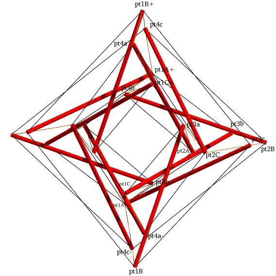
Axial View of the Four-Stage Tensegrity Torus
with Point Labels
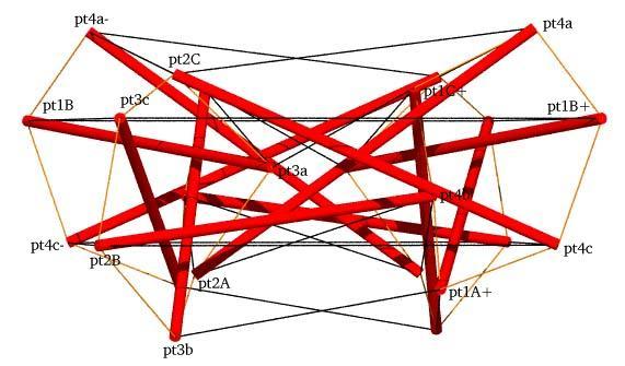
Plane View of the Four-Stage Tensegrity Torus
with Point Labels
Schematic for the Tensegrity Torus
        Member Descriptions
        [name, end point names, weight (if in objective function),
        second power of length (if a constraint), member category,
        Obj/Con/Exc (put in objective function, use as a constraint or
        exclude from computations), flags]
        For assembly purposes, only the name and end point names are
        of interest.  The other information may be of interest after
        A Practical Guide to Tensegrity Design has been consulted.

<Member> st13a pt1A  pt3c   0.0  sqr(2.5)  1 Con CalcClear Inelastic *
<Member> st24a pt2A  pt4a   0.0  sqr(2.5)  1 Con CalcClear Inelastic *

<Member> guy1a pt1A  pt3b   1.00 0.0       3 Obj *
<Member> guy2a pt2A  pt4b   1.00 + 0.50 0.0       7 Obj *

<Member> TS23a pt2A  pt3a   0.0  sqr(0.8007685)  2 Con *
<Member> tS23a pt2A  pt3b   0.0  sqr(0.8007685)  2 Con *

<Member> tT31a pt3a  pt1C+  0.60 + 0.50 0.0       3 Obj *
<Member> tT42a pt4a- pt2C   0.60 0.0       3 Obj *

<Member> TS41a pt4a  pt1B+  0.0  sqr(0.8007685)  2 Con *
<Member> tS41a pt4a  pt1C+  0.0  sqr(0.8007685)  2 Con *

<Member> st13b pt1B  pt3a   0.0  sqr(2.5)  1 Con CalcClear Inelastic *
<Member> st24b pt2B  pt4b   0.0  sqr(2.5)  1 Con CalcClear Inelastic *

<Member> guy1b pt1B  pt3c   1.00 - 0.50 0.0       3 Obj *
<Member> guy2b pt2B  pt4c   1.00 - 0.50 0.0       3 Obj *

<Member> TS23b pt2B  pt3b   0.0  sqr(0.8007685)  2 Con *
<Member> tS23b pt2B  pt3c   0.0  sqr(0.8007685)  2 Con *

<Member> tT31b pt3b  pt1A+  0.60 0.0       3 Obj *
<Member> tT42b pt4b- pt2A   0.60 + 0.50 0.0       7 Obj *

<Member> TS41b pt4b  pt1C+  0.0  sqr(0.8007685)  2 Con *
<Member> tS41b pt4b  pt1A+  0.0  sqr(0.8007685)  2 Con *

<Member> st13c pt1C  pt3b   0.0  sqr(2.5)  1 Con CalcClear Inelastic *
<Member> st24c pt2C  pt4c   0.0  sqr(2.5)  1 Con CalcClear Inelastic *

<Member> guy1c pt1C  pt3a   1.00 + 0.50 0.0       3 Obj *
<Member> guy2c pt2C  pt4a   1.00 0.0       3 Obj *

<Member> TS23c pt2C  pt3c   0.0  sqr(0.8007685)  2 Con *
<Member> tS23c pt2C  pt3a   0.0  sqr(0.8007685)  2 Con *

<Member> tT31c pt3c  pt1B+  0.60 - 0.50 0.0       3 Obj *
<Member> tT42c pt4c- pt2B   0.60 - 0.50 0.0       3 Obj *

<Member> TS41c pt4c  pt1A+  0.0  sqr(0.8007685)  2 Con *
<Member> tS41c pt4c  pt1B+  0.0  sqr(0.8007685)  2 Con *


        Rotation Matrices
        Only part of the structure is specified using the members
        above.  The rest is generated using symmetry transformations.
        Here the first symmetry transformation is specified as a 3x3
        pre-multiplication matrix in row-major format.  As with
        the members, the first item is always the label used for
        the transform.

<XMat> x1 cos(2*pi/2) (-sin(2*pi/2)) 0 sin(2*pi/2) cos(2*pi/2) 0 0 0 1


        In-Situ Member Lengths
        These are the lengths of the members when they are in place
        and prestress is applied.  The strut lengths are from
        screw-eye center to screw-eye center, as are the tendon lengths.
        These values are in model units.

    st13a:          2.5     st24a:          2.5     guy1a:      2.14766
    guy2a:      1.55457     TS23a:     0.800768     tS23a:     0.800768
    tT31a:      0.96985     tT42a:      1.67562     TS41a:     0.800768
    tS41a:     0.800768     st13b:          2.5     st24b:          2.5
    guy1b:      2.76645     guy2b:      2.76645     TS23b:     0.800769
    tS23b:     0.800768     tT31b:      1.67562     tT42b:      0.96985
    TS41b:     0.800768     tS41b:     0.800768     st13c:          2.5
    st24c:          2.5     guy1c:      1.55457     guy2c:      2.14766
    TS23c:     0.800768     tS23c:     0.800768     tT31c:      2.83827
    tT42c:      2.83827     TS41c:     0.800768     tS41c:     0.800768


        Relative Member Prestress Force Magnitudes
        These values are useful for developing an assembly
        strategy for the structure.  The tighter tendons are much
        easier to tie in place early on, while the looser tendons
        can be left to the last.  This information is also used
        to adjust tendon lengths since the measured length of a tendon
        will be shorter for a highly-stressed tendon with the same
        in-situ length as a tendon which is not so stressed.

    st13a:     -2.39294     st24a:     -3.86391     guy1a:      2.14766
    guy2a:      2.33185     TS23a:      2.20609     tS23a:      1.64125
    tT31a:      1.06684     tT42a:      1.00537     TS41a:      1.64437
    tS41a:      1.64125     st13b:     -3.14587     st24b:     -3.14587
    guy1b:      1.38323     guy2b:      1.38323     TS23b:      1.64437
    tS23b:      1.57615     tT31b:      1.00537     tT42b:      1.06684
    TS41b:      2.20609     tS41b:      1.31055     st13c:     -3.86391
    st24c:     -2.39294     guy1c:      2.33185     guy2c:      2.14766
    TS23c:      1.50937     tS23c:      1.31055     tT31c:     0.283827
    tT42c:     0.283827     TS41c:      1.50937     tS41c:      1.57615

        Average tendon force magnitude: 1.50888


        Worst-Case Clearances in Model Units
        These clearances are measured from member centerline to
        member centerline.  The labels of the two members are specified
        as well as a transformation for the second member.  If "id"
        is specified for the transformation, it means none was applied.

    0.177344    st13a     tT42b        id
    0.143459    st24a     tT31a        id
    0.148135    st24a     st24b        id
    0.123907    st24a     TS41b        id
    0.141201    st24a     st13c        id
    0.141201    st24a     st13c        x1
    0.143459    st24a     guy1c        x1
    0.148135    st13b     st13c        id
    0.143459    st13c     guy2a        id
    0.123907    st13c     TS23a        id
    0.143459    st13c     tT42b        id
    0.177344    st24c     tT31a        id


        Construction Lengths (in millimeters and halves)
        The construction length of a tendon is less than the in-situ
        length since when the tendon is measured off it isn't under
        any prestress force.  The construction length for the strut
        represents the length of a 5/16-inch-diameter wooden dowel.
        The tendons can be made of braided nylon fishing line.
        Prestress forces were assumed not to affect strut lengths.

        Elongation of Tendon of Unit Cross Section
        Under Force of Average Magnitude (fraction)> .02
        Length Scale Factor> 290/2.5
        Strut and Tendon Hub Adjustments - s;t> 5 3.5
        (The 5 mm adjustment for the strut is the amount
         the screw-eye center extends from the dowel.  The 3.5 mm
	 adjustment for the tendon is half the outer diameter of the
         screw eye.)

    st13a: 280 0     st24a: 280 0     guy1a: 235 1     guy2a: 168 0
    TS23a:  83 1     tS23a:  84 0     tT31a: 104 0     tT42a: 185 0
    TS41a:  84 0     tS41a:  84 0     st13b: 280 0     st24b: 280 0
    guy1b: 308 1     guy2b: 308 1     TS23b:  84 0     tS23b:  84 0
    tT31b: 185 0     tT42b: 104 0     TS41b:  83 1     tS41b:  84 1
    st13c: 280 0     st24c: 280 0     guy1c: 168 0     guy2c: 235 1
    TS23c:  84 0     tS23c:  84 1     tT31c: 321 0     tT42c: 321 0
    TS41c:  84 0     tS41c:  84 0
Axial View of the Four-Stage Tensegrity Torus
with Point Labels
Plane View of the Four-Stage Tensegrity Torus
with Point Labels
Schematic for the Tensegrity Torus
structure file:  torus/x3l04torus1.rc
 variable file:  torus/x3l04torus1.dat
    digit list:  src/mm.dls
|
CONTACT:
Bob Burkhardt
Tensegrity Solutions
Box 426164
Cambridge, MA 02142-0021
USA
e-mail: bobwb@juno.com