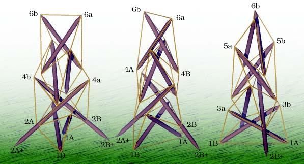
Three Views of the Bean Teepee
structure file: chain/x2l4chain1a.rc variable file: chain/x2l4chain1a.dat stress-strain chart file: v02oct_s/evans.ssc cross-section table: chain/x2l4chain1a.cst digit list file: src/standard.dls |
        Member Descriptions
        [name, end point names, weight (if in objective function),
        second power of length (if a constraint), member category,
        Obj/Con/Exc (put in objective function, use as a constraint or
        exclude from computations), flags]
        For assembly purposes, only the name and end point names are
        of interest.  The other information may be of interest after
        A Practical Guide to Tensegrity Design has been consulted.

first stage

<Member> end1     p1A  p1B   0.0  sqr(1.3*1.24030)   4 Con *

<Member> st13     p1A  p3a   0.0  sqr(1.685867)  1 Con CalcClear Inelastic *

<Member> side1a   p1A  p3b   1.0  0.0       3 Obj *
<Member> side1c   p1A  p2B   1.0  0.0       3 Obj *

<Member> gird1a   p2A  p3a   0.0  sqr(1.0)  2 Con *
<Member> gird1b   p2A  p3b   0.0  sqr(1.0)  2 Con *

second (complete) stage

<Member> st24  p2A+  p4a  0.0  sqr(1.685867*1.4146184)  1 Con CalcClear Inelastic *

<Member> side2a   p2A  p4b   1.0  0.0       3 Obj *
<Member> side2b   p4a  p3a   1.0  0.0       3 Obj *
<Member> side2c   p2A  p3B   1.0  0.0       3 Obj *

<Member> gird2a   p4a  p3B   0.0  sqr(1.0)  2 Con *
<Member> gird2b   p4a  p3A   0.0  sqr(1.0)  2 Con *

third (complete) stage

<Member> st35     p3A  p5a   0.0  sqr(1.685867)  1 Con CalcClear Inelastic *

<Member> side3a   p3A  p5b   1.0  0.0       3 Obj *
<Member> side3b   p5a  p4a   1.0  0.0       3 Obj *
<Member> side3c   p3A  p4B   1.0  0.0       3 Obj *

<Member> gird3a   p5a  p4B   0.0  sqr(1.0)  2 Con *
<Member> gird3b   p5a  p4A   0.0  sqr(1.0)  2 Con *

fourth and last stage

<Member> st46     p4A  p6a   0.0  sqr(1.685867)  1 Con CalcClear Inelastic *

<Member> side4a   p4A  p6b   1.0  0.0       3 Obj *
<Member> side4b   p6a  p5a   1.5  0.0       3 Obj *

<Member> end2     p6b  p6a   0.0  sqr(1.24030/1.3)  4 Con *


        In-Situ Member Lengths
        These are the lengths of the members when they are in place
        and prestress is applied.  The strut lengths are from
        screw-eye center to screw-eye center, as are the tendon lengths.
        These values are in model units.

     end1:      1.61239      st13:      1.68587    side1a:     0.923189
   side1c:     0.953076    gird1a:            1    gird1b:            1
     st24:      2.38486    side2a:      1.17827    side2b:      0.97929
   side2c:     0.846298    gird2a:            1    gird2b:            1
     st35:      1.68587    side3a:      1.38778    side3b:     0.998633
   side3c:     0.832481    gird3a:            1    gird3b:            1
     st46:      1.68587    side4a:      1.40257    side4b:     0.874856
     end2:     0.954077


        Relative Member Prestress Force Magnitudes
        These values are useful for developing an assembly
        strategy for the structure.  The tighter tendons are much
        easier to tie in place early on, while the looser tendons
        can be left to the last.  This information is also used
        to adjust tendon lengths since the measured length of a tendon
        will be shorter for a highly-stressed tendon with the same
        in-situ length as a tendon which is not so stressed.
        Since the symmetry transform maps end1 and end2 into
        themselves, they each represent two overlapping tendons,
        each with the force magnitude given below.  So, the total
        force is actually twice the value given for end1 and end2.

     end1:     0.707352      st13:     -2.58943    side1a:     0.923189
   side1c:     0.953076    gird1a:      1.35245    gird1b:      1.58822
     st24:     -2.59752    side2a:      1.17827    side2b:      0.97929
   side2c:     0.846298    gird2a:      1.39285    gird2b:       1.3656
     st35:     -3.56761    side3a:      1.38778    side3b:     0.998633
   side3c:     0.832481    gird3a:      1.10818    gird3b:       1.4817
     st46:     -2.98368    side4a:      1.40257    side4b:      1.31228
     end2:     0.649404

        Average tendon force magnitude: 1.13665


        Construction Lengths (in inches, 16ths and 32nds)
        The construction length of a tendon is less than the in-situ
        length since when the tendon is measured off it isn't under
        any prestress force.  The construction length for a member
        represents the distance between the locations where it
        departs from the hub.  The struts were cut from
        1-inch by 1-inch hardwood garden stakes.  The lengths below
        are specified for braided nylon twine (e.g. T.W. Evans
        #1 Braided Nylon Mason Line -- Item No. 12-503).  Its behavior
        under stress is highly non-linear, so a look-up table
        was used to compute strains.  It seems to be slightly more
        stretchy than twine composed of twisted strands
        (e.g. Wellington #18 Nylon Twine -- Prod. No. 46302).
        Prestress forces were assumed to affect tendon lengths and
        not strut lengths.

        Average Tendon Force Magnitude (chart units)> 20
        Length Scale Factor> 34/1.685867
        Strut and Tendon Hub Adjustments> 0 0.5
        (adjust the tendon lengths by subtracting a half inch from
         both ends)

     end1:  27 11 1      st13:  34  0 0    side1a:  15 15 0    side1c:  16  7 0
   gird1a:  16 14 1    gird1b:  16 11 0      st24:  48  1 1    side2a:  20  5 0
   side2b:  16 14 0    side2c:  14 10 0    gird2a:  16 14 0    gird2b:  16 14 1
     st35:  34  0 0    side3a:  23 12 1    side3b:  17  3 1    side3c:  14  6 0
   gird3a:  17  2 1    gird3b:  16 12 1      st46:  34  0 0    side4a:  24  0 0
   side4b:  14 11 1      end2:  16  2 1


        Material Quantities
        This provides an estimate of how much material will
        be needed to assemble the structure, in this case
        inches of garden stake and inches of nylon twine.
        The lengths must be adjusted to take into account the
        fact that the strut extends past the hub and some length
        of tendon is required to tie it to the strut.
        These values don't take into account that two struts
        have a significant extention to provide for the stability
        of the structure when used as a tower.

        Length Scale Factor> 34/1.685867
        Strut and Tendon Adjustments> (-1) (-6)
        (adjust the strut lengths by adding an inch to
         both ends; adjust the tendon lengths by adding
         six inches to both ends)

                    Cross
         Type     Section    Quantity Count

            4         0.5     133.629     4
            1           1     316.194     8
            3           1     589.668    20
            2           1     340.121    12
        Strts                 316.194     8
        Tndns                 996.603    36
Three Views of the Bean Teepee
structure file: chain/x2l4chain1a.rc variable file: chain/x2l4chain1a.dat stress-strain chart file: v02oct_s/evans.ssc cross-section table: chain/x2l4chain1a.cst digit list file: src/standard.dls |
CONTACT:
Bob Burkhardt
Tensegrity Solutions
Box 426164
Cambridge, MA 02142-0021
USA
e-mail: bobwb@juno.com