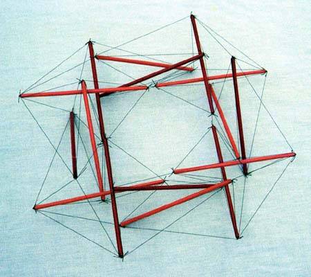
Axial View of X-Module Torus 1
with Point Labels
structure file: torus/x2l08torus1.rc
variable file: torus/x2l08torus1.dat
digit list: src/mm.dls
|
        Member Descriptions
        [name, end point names, weight (if in objective function),
        second power of length (if a constraint), member category,
        Obj/Con/Exc (put in objective function, use as a constraint or
        exclude from computations), flags]
        For assembly purposes, only the name and end point names are
        of interest.  The other information may be of interest after
        A Practical Guide to Tensegrity Design has been consulted.

<Member> st13p    pt1A  pt3a   0.0  sqr(2.0)  1 Con CalcClear Inelastic *
<Member> st24p    pt2A  pt4a   0.0  sqr(2.0)  1 Con CalcClear Inelastic *

<Member> gird2ap  pt4a  pt1B+  0.0  sqr(1.0)  2 Con *
<Member> gird2bp  pt4a  pt1A+  0.0  sqr(1.0)  2 Con *

<Member> side2ap  pt2A  pt4b   1.6*1.2  0.0   3 Obj *
<Member> side2bp  pt4a  pt3a   1.0/1.6  0.0   3 Obj *
<Member> side2cp  pt2A  pt1B+  1.6*1.0  0.0   3 Obj *

<Member> gird1ap  pt2A  pt3a   0.0  sqr(1.0)  2 Con *
<Member> gird1bp  pt2A  pt3b   0.0  sqr(1.0)  2 Con *

<Member> side1ap  pt1A  pt3b   1.2      0.0   3 Obj *
<Member> side1bp  pt3a  pt4a-  1.0/1.6  0.0   3 Obj *
<Member> side1cp  pt1A  pt2B   1.0/1.6  0.0   3 Obj *

<Member> st13q    pt1B  pt3b   0.0  sqr(2.0)  1 Con CalcClear Inelastic *
<Member> st24q    pt2B  pt4b   0.0  sqr(2.0)  1 Con CalcClear Inelastic *

<Member> gird2aq  pt4b  pt1A+  0.0  sqr(1.0)  2 Con *
<Member> gird2bq  pt4b  pt1B+  0.0  sqr(1.0)  2 Con *

<Member> side2aq  pt2B  pt4a   1.2/1.6  0.0   3 Obj *
<Member> side2bq  pt4b  pt3b   1.6*1.0  0.0   3 Obj *
<Member> side2cq  pt2B  pt1A+  1.0/1.6  0.0   3 Obj *

<Member> gird1aq  pt2B  pt3b   0.0  sqr(1.0)  2 Con *
<Member> gird1bq  pt2B  pt3a   0.0  sqr(1.0)  2 Con *

<Member> side1aq  pt1B  pt3a   1.2      0.0   3 Obj *
<Member> side1bq  pt3b  pt4b-  1.3*1.0  0.0   3 Obj *
<Member> side1cq  pt1B  pt2A   1.3*1.0  0.0   3 Obj *
        Special Note
        There are member pairs here which are symmetric, for which the symmetry
        has not been captured in the nominal symmetry transformations.  This
        symmetry was preserved in the computations by treating the pairs
        symmetrically.

        The symmetric pairs are:

        side1aq -- side1ap, side1bq -- side1cq, side1bp -- side1cp,
        side2cp -- side2bq, side2bp -- side2cq,
        gird1ap -- gird2aq, gird1bp -- gird2bq, gird1aq -- gird2ap,
        gird1bq -- gird2bp, st24p -- st24q
        Rotation Matrices and Transform Points
        Only part of the structure is specified using the members
        above.  The rest is generated using symmetry transformations.
        Here the first symmetry transformation is specified as a 3 by 3
        pre-multiplication matrix in row-major format.  Others are
        constructed by multiplying the first one by itself.  As with
        the members, the first item is always the label used for
        the transform.  In this case the base transform (specified
        in <XMat>) is just a rotation about the z-axis by 90°.

# rotation matrices
<XMat> x1 cos(2*pi/4) (-sin(2*pi/4)) 0 sin(2*pi/4) cos(2*pi/4) 0 0 0 1
<CompositeXform> x2 x1 x1
<CompositeXform> x3 x1 x2

# transform points
<XformPt> pt1A+ pt1A  x1
<XformPt> pt1B+ pt1B  x1
<XformPt> pt4a- pt4a  x3
<XformPt> pt4b- pt4b  x3
        In-Situ Member Lengths
        These are the lengths of the members when they are in place
        and prestress is applied.  The strut lengths are from
        pin insertion point to pin insertion point, as are the tendon lengths.
        These values are in model units.

    st13p:            2     st24p:            2   gird2ap:            1
  gird2bp:            1   side2ap:      1.15998   side2bp:      1.36547
  side2cp:        1.065   gird1ap:            1   gird1bp:            1
  side1ap:      1.78993   side1bp:      1.95378   side1cp:      1.95378
    st13q:            2     st24q:            2   gird2aq:            1
  gird2bq:            1   side2aq:      1.64205   side2bq:        1.065
  side2cq:      1.36547   gird1aq:            1   gird1bq:            1
  side1aq:      1.78993   side1bq:      1.06234   side1cq:      1.06234
        Relative Member Prestress Force Magnitudes
        These values are useful for developing an assembly
        strategy for the structure.  The tighter tendons are much
        easier to tie in place early on, while the looser tendons
        can be left to the last.  This information is also used
        to adjust tendon lengths since the measured length of a tendon
        will be shorter for a highly-stressed tendon with the same
        in-situ length as a tendon which is not so stressed.

    st13p:     -4.37614     st24p:     -5.14993   gird2ap:      2.18165
  gird2bp:      1.31648   side2ap:      2.22716   side2bp:      0.85342
  side2cp:      1.70400   gird1ap:      1.76087   gird1bp:      2.25247
  side1ap:      2.14791   side1bp:      1.22111   side1cp:      1.22111
    st13q:     -5.81593     st24q:     -5.14993   gird2aq:      1.76087
  gird2bq:      2.25247   side2aq:      1.23154   side2bq:      1.70400
  side2cq:      0.85342   gird1aq:      2.18165   gird1bq:      1.31648
  side1aq:      2.14791   side1bq:      1.38105   side1cq:      1.38105

        Average tendon force magnitude: 1.65483
        Worst-Case Clearances in Model Units
        These clearances are measured from member centerline to
        member centerline.  The labels of the two members are specified
        as well as a transformation for the second member.  If "id"
        is specified for the transformation, it means none was applied.
        The worst-case values are provided for strut-strut convergences
        and then for the strut-tendon convergences.

    0.231115    st24p     st13q        x1
    0.231115    st13q     st24q        id
    0.215367    st24p   gird2bq        id
    0.215367    st24q   gird1bp        id
    0.237170    st24p   side1bq        id
        Construction Lengths (in millimeters and halves)
        The construction length of a tendon is less than the in-situ
        length since when the tendon is measured off it isn't under
        any prestress force.  The construction length for the strut
        represents the length of the ¼-inch-diameter wooden dowel.
        The tendons were made of 15-lb.-test braided nylon fishing line.
        In this case, the attachment point at the hubs was a simple
        metal pin stuck into the end of the strut, so no member-length
        adjustments were necessary.  Prestress forces are assumed
        not to affect strut lengths.

        Elongation of Tendon of Unit Cross Section
        Under Force of Average Magnitude (fraction)> .02
        Length Scale Factor> 200/2
        Strut and Tendon Hub Adjustments - s;t> 0 0

    st13p: 200 0     st24p: 200 0   gird2ap:  97 1   gird2bp:  98 1
  side2ap: 113 0   side2bp: 135 0   side2cp: 104 1   gird1ap:  98 0
  gird1bp:  97 1   side1ap: 174 1   side1bp: 192 1   side1cp: 192 1
    st13q: 200 0     st24q: 200 0   gird2aq:  98 0   gird2bq:  97 1
  side2aq: 162 0   side2bq: 104 1   side2cq: 135 0   gird1aq:  97 1
  gird1bq:  98 1   side1aq: 174 1   side1bq: 104 1   side1cq: 104 1
Axial View of X-Module Torus 1
with Point Labels
structure file:  torus/x2l08torus1.rc
 variable file:  torus/x2l08torus1.dat
    digit list:  src/mm.dls
|
|
CONTACT: Bob Burkhardt Tensegrity Solutions Box 426164 Cambridge, MA 02142-0021 USA e-mail: bobwb@juno.com |