TENSEGRITIES
by Jan Marcus
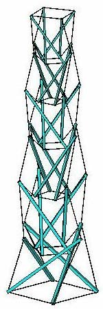
This tower, approximately 4.5 meters high, I used in meetings with users of Finite-Element-Method computer programs to verify the results of such programs. I also erected it in the front garden of my home in Beverwijk, the Netherlands (see photo). Because structures are more interesting with some background information, I describe in this short article the "ins and outs" of this one.
Why?
In a Dutch technical periodical from the late sixties, there was an article
concerning a marvellous tower of Kenneth Snelson. In the sculpture-garden
of the Kröller-Müller museum in the Netherlands, a so-called "Needle Tower"
was erected. This marvellous tower, about 18 meters high,
was stable, but appeared to float in the air. It consisted of some thirty
aluminium rods linked by some ninety wires.
A sentence in that article did not seem correct to me. Kenneth Snelson asserted that no engineer could analyse this tower. Concerning analysis, he meant the stresses and displacements of the structure. Of course, as a young engineer, I did not agree! At that moment, however, I had no time to do a test. Years later, in the winter of 1978, I remembered this article. I could not find it anywhere, so I had to recreate the design of the tower on my own. I remembered that the tower consisted of only rods and wires, and the rods did not touch each other.
How?
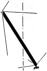
It is possible to erect a mast or stick using three wires;
more are not needed, fewer are not possible. If you do not put the lower part
of this mast or stick on the ground but use also three wires to lift it
from the ground, the mast stands stable in the space.
See the left figure below. By twisting this figure
0, 90 , 180 and 270 degrees around the vertical dotted line,
the right figure below arises.
 |
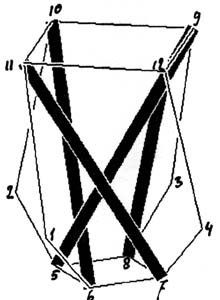 |
The right figure is a single story of the tower. Of course the length of the wires cannot be chosen randomly. With a little engineering knowledge you can find out that, for example, point 1 must lie in the plane through the points 7-11-9. With this data it is possible to determine the coordinates of all the nodes. By fixing the points 1 through 4 in space, one can use, for example, the upper part (points 9 through 12) to support the next story. This type of structure is called tensegrity (tensional integrity). Anthony Pugh, in his book An introduction to tensegrity gives the following definition:
A tensegrity system is established when a set of discontinuous compressive components interacts with a set of continuous tensile components to define a stable volume in space.
I add to that definition: a minimum number of tensile components. That means, therefore, that every rod is linked with only six wires. Snelson generally uses eight and sometimes even ten wires. That is, therefore, too much. You can see in the Needle Tower a number of wires slack, you do not need them! A disadvantage of my minimum number of tensile components is that the collapse of one rod or one wire leads to the collapse of the whole tower! That once happened with my tower!
Analysis
The reason for this whole exercise was that Kenneth Snelson
asserted that no engineer would be able analyse this tower.
It should be clear that finally I have succeeded in analyzing the stresses
and displacements in all parts of the tower.
I must say though that, at that time, Snelson was right with his observation.
(During a storm on Sunday 27 October 2002 the Needle Tower has succumbed!)
Just halfway through the seventies, computer programs became available for the
analysis of this type of structure.
These so-called geometric non-linear approaches are now available for
MSC/NASTRAN and ANSYS. For the first analysis I made, I had to use
MSC/NASTRAN for some hours on a very large mainframe.
Today I use ANSYS on my PC for a couple of minutes to do the same analysis!
Here is an example of the use of ANSYS to analyze a tensegrity prism:
/title,Driehoekige tensegrity met ls=1500, lo=800 en lb=600 /prep7 *set,ls,1500 *set,lo,800 *set,lb,600 *set,h,sqrt(ls*ls-lo*lo/4-(lo*sqrt(3)/6+lb*sqrt(3)/3)*(lo*sqrt(3)/6+lb*sqrt(3)/3)) k,1,-lo/2,-lo*sqrt(3)/6,0 k,2,lo/2,-lo*sqrt(3)/6,0 k,3,0,lo*sqrt(3)/3,0 k,4,-lb/2,-lb*sqrt(3)/6,h k,5,lb/2,-lb*sqrt(3)/6,h k,6,0,lb*sqrt(3)/3,h l,1,2 l,2,3 l,3,1 l,4,5 l,5,6 l,6,4 l,1,4 l,2,5 l,3,6 l,1,5 l,2,6 l,3,4 et,,link8 esize,2*ls mp,ex,,100000 r,1,10 r,2,.1,.5 r,3,2500 real,1 lmesh,1,6 real,2 lmesh,7,9 real,3 lmesh,10,12 /eshape,1,1 eplot dk,1,,,,,ux,uy,uz dk,2,,,,,uy,uz dk,3,,,,,uz fini /solu nlgeom,on solve fini /post1 set pldisp |

Point Labels

Initial Configuration
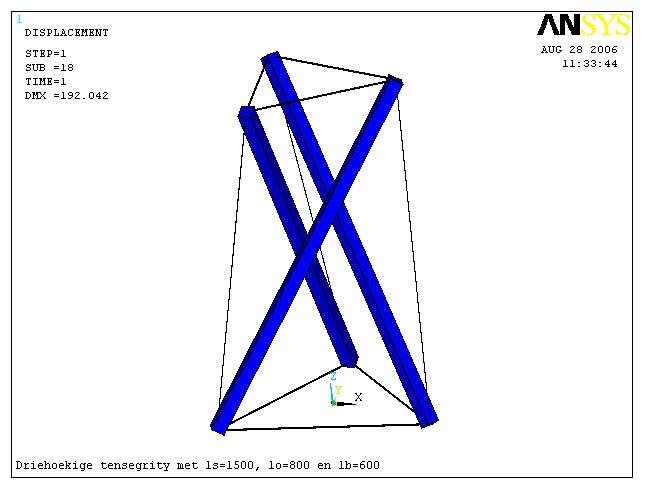
Final Configuration
By modifying ls and/or lo and/or lb, I can get a nice looking tensegrity.