A Technology for Designing Tensegrity Domes and Spheres
Robert Burkhardt
Tensegrity Solutions
Box 426164
Cambridge, MA 02142-0021
USA
bobwb@juno.com
Last revision: June 7, 2007
Abstract
Robert Burkhardt
Tensegrity Solutions
Box 426164
Cambridge, MA 02142-0021
USA
bobwb@juno.com
Last revision: June 7, 2007
Abstract
A technology based on tensegrity techniques is proposed for the economical construction of tough, rigid, large-scale domes. Sample structures, possible applications, related technologies and plans for future research are also presented.
The technology is of the double-layer type where an outer and an inner layer of tendons are inter-connected by struts and additional tendons. Struts and tendons are organized to emphasize triangulation and lateral transmission of exogenous loads within the space frame. It is hypothesized, and preliminary testing has verified, that this arrangement will result in a structure with improved stiffness. If more thorough testing verifies this hypothesis is correct, this technology will overcome a shortcoming which plagues tensegrity designs, while retaining the ethereality and resilience which recommends these designs.
The development of a structural technology to economically encompass large areas would be useful for warehouses, permanent or temporary protection for archaeological and other vulnerable sites, large-scale electrical or electromagnetic shielding and exclusion or containment of flying animals or other objects. Over cities, structures based on such a technology could serve as frameworks in which environmental control, energy transformation and food production facilities could be embedded.
|
Key Words:
tensegrity, space frame, structure, truss, dome, architecture,
suspension, tensile, software
2.1 Motivation3 Possible Applications
2.2 Summary of Research Results
2.3 Tensegrity Truss Technology
2.4 Form-Finding Technology
2.5 Analysis of Exogenous Loads
2.6 Design Examples
6.1 Applications7 Tensegrity Solutions: Background Information
6.2 Computation
6.3 Design
9.1 Panel Summary
9.2 Comments of First Respondent
9.3 Comments of Second Respondent
9.4 Comments of Third Respondent
Oct4v
: 4ν Double-Layer Sphere
Oct2v
: 2ν Double-Layer Sphere
Tripod
: Tensegrity Tripod
Oct6vnet
: 6ν Octahedral Tensegrity Network
Oct6vtri
: Spherical Assembly of Tensegrity Tripods
Tripods
: Planar Assembly of Tensegrity Tripods
Oct10vnt
: 10ν Octahedral Tensegrity Net
Oct10vd
: 10ν Double-Layer Dome (Side View)
Oct8vd
: 8ν Double-Layer Dome
Oct4vd
: 4ν Double-Layer Dome
The technology discussed in this prospectus is aimed at facilitating the economical construction of tough, rigid, large-scale domes. The technology is based on the tensegrity approach to space frame design which strictly segregates compressive and tensile forces among the members of the frame. This minimizes the number of members which need to sustain compressive forces. The minimization of these more massive and visually intrusive components results in most frame members being lighter-weight more-transparent tensile components.
Since the introduction of the tensegrity concept in the 1940's, many models have been built.[See Fuller73 pp. 164-169 for several early examples.] However, as R. Motro notes in his survey "Tensegrity Systems: State of the Art":
...there has not been much application of the tensegrity principle in the construction field. ...examples...have generally remained at prototype state for lack of adequate technological design studies.[Motro92, p. 81]
This is not to say that there have been no practical structures built using the tensegrity principal. Effective use of tensegrity principles has been made by Geiger and Levy to design roofs which cover large areas.[Campbell94 reviews these approaches.] However these approaches result in essentially composite structures where a substantial portion of the structure is fabricated using non-tensegrity technologies. Thus these structures do not take complete advantage of what the tensegrity technique has to offer.
Structures based on the technology proposed here maximally employ tensegrity principles. Tensegrity methods derive maximal structural performance from the materials employed. This is due to their maximization of the tensile components of the structure which allows them to take full advantage of the progress has been made in deriving larger tensile strengths from materials.[See Davis70 pp. 2-3 for data on metals, and Jang94 for the huge tensile strengths obtained from fibers of various materials.] The resulting light weight allows tensegrity structures to encompass very large areas with minimal support at their perimeters, obviating the "heavy anchorage devices"[Motro87, p. 43] needed for support with some cable-based technologies, or extensive support structures needed by the composite structures discussed above.
This prospectus focuses on the construction of tensegrity domes since these are most useful in a terrestrial context. However, since the technology proposed conceives domes as truncated spheres, the technology can easily be applied to the design of spheres as well.
One characteristic of materials research has been the increasing tensile performance which researchers have been able to extract from materials through various fabrication technologies. In the construction sector, this performance can be harnessed by structural technologies which rely predominantly on tensile components. Tensegrity designs represent such a technology.
The primary obstacles to the practical application of tensegrity technology have been:
2.2 Summary of Research Results
Much progress has been made by Tensegrity Solutions and others in overcoming these obstacles. The research of Tensegrity Solutions in the area of tensegrity design represents the focusing of results from several disciplines (computer science, mechanical engineering, mathematical programming, economics) on problems in this area. This research has resulted in flexible techniques for designing and analyzing tensegrity structures as well as several design innovations which apply to these structures. Many of the problems related to the practical realization of tensegrity structures have already been solved by Tensegrity Solutions. Specifically, the following solutions have been obtained:
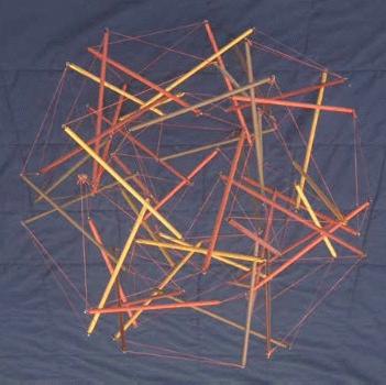
Figure Oct4v
4ν Double-Layer Sphere
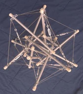
Figure Oct2v
2ν Double-Layer Sphere
2.3 Tensegrity Truss Technology
The starting point of Tensegrity Solutions' system for designing a tensegrity truss is the tensegrity tripod[Burkhardt04] and tensegrity networks derived from geodesic polyhedra.[Pugh76, pp. 28-30] A tensegrity tripod encompasses six tendons. Three tendons, referred to here as "apex" tendons, bind the three struts together at one end to form a triangle which represents the apex of the tripod. Each of the other three tendons, referred to here as "interlayer" tendons, connects the apex end of one strut to the the non-apex end of an adjacent strut in the tripod. This forms an additional three triangles, each triangle containing an apex tendon, an interlayer tendon and a strut. Figure Tripod shows a tripod; Figure Oct6vnet shows a tensegrity network based on a 6ν subdivisioning of an octahedron, and Figure Oct6vtri shows a spherical assembly of tripods embedded in the tensegrity network. To enhance diagrammatical clarity, the back halves of Figures Oct6vnet and Oct6vtri have been sliced away. A dome can be induced by truncating the sphere.
Figure Tripod
Tensegrity Tripod
Figure Oct6vnet
6ν Octahedral Tensegrity Network
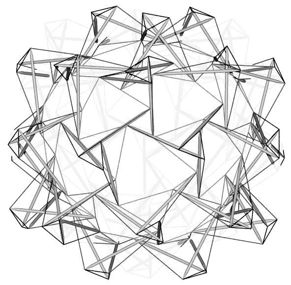
Figure Oct6vtri
Spherical Assembly of Tensegrity Tripods
In addition, each inner tendon triangle where the struts of three tripods converge can be viewed as the apex of an inward-pointing tripod. Adding the corresponding interlayer tendons to complete these tripods provides more interlayer triangulation, and thus more reinforcement of the structure. Finally, the outer layer of tendons can be completed by connecting the apexes of the original outward-pointing tripods using tendon triangles. This completes the truss. It is hypothesized that this arrangement will result in a structure of superior stiffness. In this configuration, each strut is secured by 12 tendons. It is worth noting that this is precisely the minimum number of tendons Fuller has experimentally found to be necessary to rigidly fix one system in its relationship to a surrounding system.[Fuller75, pp. 105-107]
Figure Tripods shows what the complete truss looks like in a planar context. The truss looks the same regardless of which side of the plane it is being viewed from. This apparently planar section of truss can also be conceived as a small section of the surface of a very large double-layer sphere. In this context, the small section looks the same regardless of whether it is being viewed from inside or outside the sphere.
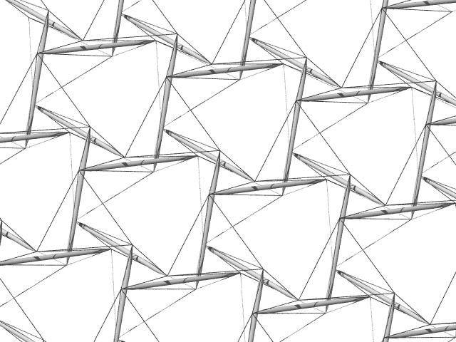
Figure Tripods
Planar Assembly of Tensegrity Tripods
Tensegrity Solutions' technique can be applied to any tensegrity network which can be dividing into alternating polylaterals.[A "polylateral" is a subset of a tensegrity. The subset is a ring composed of hubs of the tensegrity and includes tendons which continuously connect the hubs pair-wise. A "hub" is any location where tendons and struts are connected to each other. Each included tendon connects two hubs, and each hub is connected to two tendons. The minimum polylateral is a triangle of three hubs connected by three tendons.] However, in the interests of maximizing stiffness and minimizing strut density, alternating triangles seem the best way to go. In at least one situation, Hanaor has experimentally verified the preferability of triangular networks on the basis of stiffness.[Hanaor87, p. 40]
In the spherical context, the limitation to networks of alternating triangles essentially eliminates all but the octahedron as possible bases for a network. Figure Oct10vnt diagrams a 10ν version of such a network as it appears when projected onto a sphere. This has its disadvantages since the octahedron has a much more faceted look to it than the icosahedron. An icosahedron would be the preferred basis if it were feasible. This means adjustments must be made in the shape finding procedure so a spherical looking result is obtained. An octahedral basis also yields a lot of member activity at the vertexes which must be resolved. Tensegrity Solutions has developed design methodologies which effectively solve both these problems.
In addition to developing an effective double-layer topology for tensegrity domes, Tensegrity Solutions has developed very flexible techniques for form finding. These techniques are based on the mathematical programming view of tensegrity as propounded in Burkhardt04. Form finding is viewed as the solution of a non-linear mathematical programming problem whose most general statement is:
| minimize | obj = w1(l1)2 + ··· + wM(lM)2 |
| Coordinate values |
|
| subject to |
|
| Member constraints: |
|
| ± (lbarM+1)2 ≥
± (lM+1)2 |
|
| ··· |
|
| ± (lbarN)2 ≥
± (lN)2 |
|
| Symmetry constraints: |
|
| 0 = s1(···) |
|
| ··· |
|
| 0 = sK(···) |
|
| Determinacy and other constraints: |
|
| 0 = d1(···) | |
| ··· | |
| 0 = dQ(···) |
where:
M = number of members in the objective function
N = number of members in the model
K = number of symmetry constraints
Q = number of determinacy and other constraints
The phrase "Coordinate values" appearing under "minimize" indicates that the coordinate values are the control variables of the minimization problem. These are the values which are changed (in accordance with the constraints) to find a minimum value for obj.
lm stands for the length of member m, and wm is the constant weight on the second power of lm in the objective function. wm is negative if member m is a strut, positive otherwise. These weights provide maximum control over the characteristics of the resulting solution. Just about any feasible tensegrity configuration can be reached by choosing the members to include in the objective function and their weights appropriately.
In the member constraints, lbarn is a positive constant value. "-" precedes (ln)2 and (lbarn)2 if member n is a strut and "+" precedes them if member n is a tendon. In the other constraints, sk(···) and dq(···) are (most likely linear) functions of the coordinate values.
Figure Oct10vnt
10ν Octahedral Tensegrity Network
Tensegrity Solutions has developed exact and penalty methods for solving this problem. The technique for the exact method is based on ideas in Luenberger's book[Luenberger73] and some matrix techniques. The penalty method is implemented as described in Luenberger[Luenberger73, pp. 278-280]. The penalty method is especially advantageous in initial iterations since it doesn't require the constraints to be exactly met. The exact method yields more precise results and can be used to fine tune a result. In both cases, the design software allows the solution to be derived using either the PARTAN method[Luenberger73, pp. 184-186] or the Fletcher-Reeves method[Luenberger73, p. 182] in conjunction with a custom line-search technique.
A corollary to this research showed that the relative prestress forces in a structure's members (also known as "self-stress") can be computed from the Lagrange multipliers of the resulting solution instead of going through the more standard procedure of solving the matrix of force vectors.
2.5 Analysis of Exogenous Loads
To analyze the effects of exogenous loads on a structure's members, a different conceptual framework is used. For this purpose, a structure is viewed as a flexibly-jointed set of elastic and fixed-length members, the tendons being the elastic members, and the struts being the fixed-length members. The solution of the mathematical programming problem outlined above and the accompanying prestress forces provide a valid initial solution for the equations developed to compute the effects of exogenous loads. The vectors representing the exogenous load are then introduced, and the equation system is solved using Newton techniques to arrive at values for the resultant member forces.
A representation of a dome which utilitizes Tensegrity Solutions' technology appears in Figure Oct10vd.
Figure Oct10vd
10ν Double-Layer Dome (Side View)
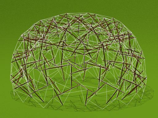
A photograph of a lower-frequency dome which has actually been built is shown in Figure Oct8vd. It is composed of 102 one-inch by one-inch by four-foot (25.4 mm by 25.4 mm by 1.22 m) hardwood stakes and 570 nylon-twine tendons of various lengths.
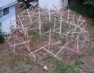
Figure Oct8vd
8ν Double-Layer Dome
A photograph of a very-low-frequency dome is shown in Figure Oct4vd. It is composed of 27 one-inch by one-inch by three-foot (25.4 mm by 25.4 mm by 0.91 m) hardwood stakes and 174 nylon-twine tendons of various lengths. At this low frequency, the interior space is fairly minimal in comparison with the volume of the dome as a whole. This model was constructed mainly to test software predictions and develop assembly procedures.
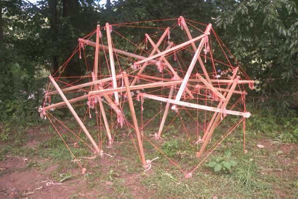
Figure Oct4vd
4ν Double-Layer Dome
This research was inspired by Buckminster Fuller's claim that structures based on tensegrity technology could be used to build domes which could provide environmental control for entire cities. Brain-storming sessions have yielded additional possibilities for the structural technology outlined in this prospectus. The resulting list represents an initial attempt to identify applications for which the technology would be suitable. As the technology develops and is tested against them, some or all of the applications may be winnowed out and other suitable applications not in the list may become apparent. The current list is as follows:
A more conservative list of applications can be found in Ariel Hanaor's article "Tensegrity: Theory and Application".[Hanaor97]
At a gross level, related non-tensegrity technologies (RNTTs) for economically enclosing large areas can be roughly sorted into two categories:
Related tensegrity technologies (RTTs) can be divided into five categories. They are ordered with the technologies which have yielded more practical structures toward the beginning.
The the tensegrity approach has the following advantages over the non-tensegrity approaches:
The relationship of the tensegrity approach proposed here over related tensegrity technologies can be summarized as follows:
Tensegrity Solutions' most fundamental need is for the development or location of a concrete design problem where the proposed technology can be applied to enough advantage that it would be adopted.
Another focus of future research will be to utilize the software tools developed by Tensegrity Solutions to analyze the load-bearing capabilities of domes designed using Tensegrity Solutions' and alternative technologies. Of particular interest is how these capabilities change with the frequency of a dome. For the technology to be useful, it must exhibit desirable characteristics at very large scales.
To carry out this research, Tensegrity Solutions' computing facilities need to be upgraded, and the software needs to be enhanced as well. A machine able to accommodate C++ software, supply abundant random-access memory and advanced floating-point capability is needed. Current plans are to acquire hardware based on the Alpha chip with Linux and/or Windows NT-based software.
Another critical need is for outside consultants to assist in the details of the design of tensegrity solutions and comment on the analysis techniques used by Tensegrity Solutions. Tensegrity Solutions' primary expertise is theoretical. Outside consultants are needed to identify appropriate ways of realizing the foundation, joinery and surfacing of a solution. In addition, they can suggest ways in which Tensegrity Solutions' procedures can be better brought into line with standard architectural and structural engineering practices.
Tensegrity Solutions is a spin off of Software Services which provides computer-related instruction and application software design and coding services and has provided computer support for the research activities outlined in this prospectus. These activities in turn have provided Software Services with a laboratory for testing various approaches to software design and as a test bed for various optimization products.
Robert Burkhardt is the principal of Tensegrity Solutions. He received a B.A. in economics from the University of California at Irvine in 1975 and attended graduate school in economics for five years at the Massachusetts Institute of Technology. His fields of concentration at MIT were monetary economics and econometrics. The background in optimization and mathematical programming received at MIT is responsible for much of his approach to tensegrity design.
He has taught computer science courses at Boston University and the Lowell Institute School (Computer Graphics, C Programming, C++ Programming, X Window Programming, BASIC). He has fulfilled contracts for software design and implementation for Computervision Corporation (interactive graphics metafile display) and Carvajal, S.A. (software to create, update, maintain and process data for a Spanish-language dictionary). He worked as a software engineer for Gamesville.com for three years.
He has been doing research in the area of tensegrity design since 1981 and on double-layer structures since 1985. Many of the results of this research are summarized in Section 2.2. He has gathered together the results of much of this research into a book.[Burkhardt04]
[Argyris72]
Argyris, J. H. and D. W. Scharpf, "Large Deflection Analysis of
Prestressed Networks", Journal of the Structural Division,
American Society of Civil Engineers,
Vol. 98 (ST3), pp. 633-654 (1972).
[Burkhardt04]
Burkhardt, R. W.,
A
Practical Guide to Tensegrity Design (2nd edition),
Cambridge, Massachusetts: Tensegrity Solutions, 2004.
[Campbell94]
Campbell, David M. et al., "Effects of Spatial
Triangulation on the Behavior of `Tensegrity' Domes," in John F. Abel et al.,
ed., Spatial, Lattice and Tension Structures: Proceedings of the
IASS-ASCE International Symposium 1994,
American Society of Civil Engineers, 1994.
[Davis70]
Davis, LeRoy and Samuel Bradstreet,
Metal and Ceramic Matrix Composites,
Boston: Cahners Publ. Co., Inc., c1970.
[Emmerich88]
Emmerich, David Georges,
Structures Tendues et Autotendantes,
Paris, France: Ecole d'Architecture de Paris la Villette, 1988.
[Fuller79]
Fuller, R. B., Synergetics2: Further Explorations in the
Geometry of Thinking, New York: MacMillan Publishing Co., Inc., 1979.
[Fuller75]
Fuller, R. B., Synergetics: Explorations in the
Geometry of Thinking, New York: MacMillan Publishing Co., Inc., 1975.
[Fuller73]
Fuller, R. B. and R. Marks, The Dymaxion World of
Buckminster Fuller, Garden City, New York: Anchor Books, 1973.
[Hanaor97]
Hanaor, Ariel, "Tensegrity: Theory and Application,"
Chapter 13 (pp. 385-408) in J. François Gabriel,
Beyond the Cube: The Architecture of Space Frames and Polyhedra,
New York: John Wiley & Sons, Inc., 1997.
[Hanaor92]
Hanaor, A., "Aspects of Design of Double-Layer
Tensegrity Domes," International Journal of Space Structures, Vol. 7,
pp. 101-113 (1992).
[Hanaor87]
Hanaor, A., "Preliminary Investigation of Double-Layer
Tensegrities," in H.V. Topping, ed., Proceedings of
International Conference on the
Design and Construction of Non-conventional Structures (Vol. 2),
Edinburgh, Scotland: Civil-Comp Press, 1987.
[Jang94]
Jang, Bor Z., Advanced polymer composites,
Materials Park, Ohio: ASM International, 1994.
[Kelly92]
Kelly, K., "Biosphere 2 at One," Whole Earth Review,
Winter 1992, pp. 90-105.
[Kenner76]
Kenner, H., Geodesic Math and How to Use It,
Berkeley, California: University of California Press, 1976.
[Luenberger73]
Luenberger, D. G., Introduction to Linear and
Nonlinear Programming, Reading, Massachusetts:
Addison-Wesley Publishing Co., 1973.
[Makowski65]
Makowski, Z.S., Steel Space Structures,
London: Michael Joseph Ltd, 1965.
[Motro94]
Motro, René et al.,
"Form Finding Numerical Methods for Tensegrity Systems",
in John F. Abel et al.,
ed., Spatial, Lattice and Tension Structures: Proceedings of the
IASS-ASCE International Symposium 1994,
American Society of Civil Engineers, 1994.
[Motro92]
Motro, R., "Tensegrity Systems: The State of the Art,"
International Journal of Space Structures,
Vol. 7, pp. 75-84 (1992).
[Motro87]
Motro, R., "Tensegrity Systems for Double-Layer Space
Structures," in H.V. Topping, ed., Proceedings of
International Conference on the
Design and Construction of Non-conventional Structures (Vol. 2),
Edinburgh, Scotland: Civil-Comp Press, 1987.
[Otto73]
Otto, Frei, ed., Tensile structures; design, structure,
and calculation of buildings of cables, nets, and membranes,
Cambridge, Massachusetts: MIT Press, 1973.
[Otto82]
Otto, Frei, Natürliche Konstruktionen,
Stuttgart: Deutsche Verlags-Anstalt, 1982.
[Pellegrino86]
Pellegrino, S. and C. R. Calladine, "Matrix Analysis
of Statically and Kinematically Indeterminate Frameworks", International
Journal of Solids and Structures,
Vol. 22, No. 4, pp. 409-428 (1986).
[Pugh76]
Hugh, A., An Introduction to Tensegrity,
Berkeley, California: University of California Press, 1976.
[Saka97]
Saka, T. and Y. Taniguchi, "Damage to Spatial Structures by the
1995 Hyoguken-Nanbu Earthquake in Japan,"
International Journal of Space Structures, Vol. 12, Nos. 3&4,
pp. 125-147 (1997).
[Vilnay90]
Vilnay, Oren, Cable Nets and Tensegric Shells:
Analysis and Design Applications, New York: Ellis Horwood, 1990.
The following comments were received when an initial version of this prospectus was sent in response to a solicitation by the National Science Foundation's Small Business Innovation Research Program.
Proposal Number: 9660694
Principal Investigator: Burkhardt
Company Name: Safeware Service (sic)
Panel # and Name: 23-5, Civil and Mechanical Systems - Structures
Panel Date: September 23-24, 1996
SUMMARY
Further research on the static's and dynamics of "tensegrity" systems is needed because such systems are being widely used for longer spans.
The P. I. does not appear to have the expertise to perform an engineering evaluation of "tensegrities". However he has thought about their geometry and may have developed innovative forms. He is encouraged to team-up with a structural engineering firm (there are many notable ones in the Boston/Cambridge area) and resubmit an SBIR proposal.
9.2 Comments of First Respondent
Total Score 11 (Max 25)
OVERALL RATING: Fair
9.3 Comments of Second Respondent
Total Score 16 (Max 25)
OVERALL RATING: Good
9.4 Comments of Third Respondent
Total Score 8 (Max 25)
OVERALL RATING: Poor
Additional analysis of respondent information provided by
Tensegrity Solutions:
AVERAGE OF THREE RESPONDENT TOTAL SCORES: 11.3 (Max 25)
OVERALL RATING CORRESPONDING TO THIS AVERAGE: Fair
See also the Synergetics Gallery.